3 Component Names and Settings
11
3 Component Names and Settings
3.1 Component Names
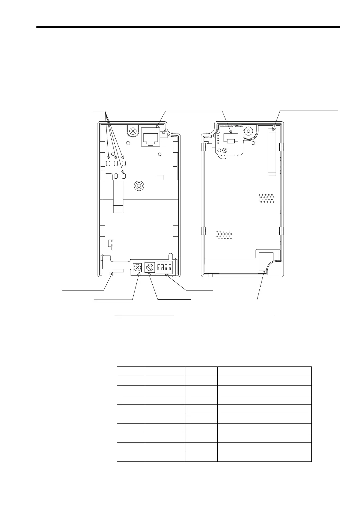
The following diagram shows the SI-T/V7 Unit external appearance and component names.
3.2 Communications Connectors (CN2)
The communications connectors connect the SI-T/V7 Unit to the communications lines of
the MECHATROLINK-I or MECHATROLINK-II . The following table shows the pin num-
bers and their functions.
5.5
mm
LED
Communications
connector (CN2)
Communications
connector (CN2)
DIP switch
Modular plug (CN10)
Rotary switch
Optional connector (CN1)
Front of the SI-T/V7 Unit
Ground terminal
Rear of the SI-T/V7 Unit
Pin No. Signal Name I/O Function
A1 (NC) −
Not used.
A2 SRD− I/O
Send/receive data (-)
A3 SRD+ I/O
Send/receive data (+)
A4 (NC) −
Not used.
B1 (NC) −
Not used.
B2 SRD− I/O
Send/receive data (-)
B3 SRD+ I/O
Send/receive data (+)
B4 (NC) −
Not used.
Shell Shield −
Not used.