25
PUC2 Multipin
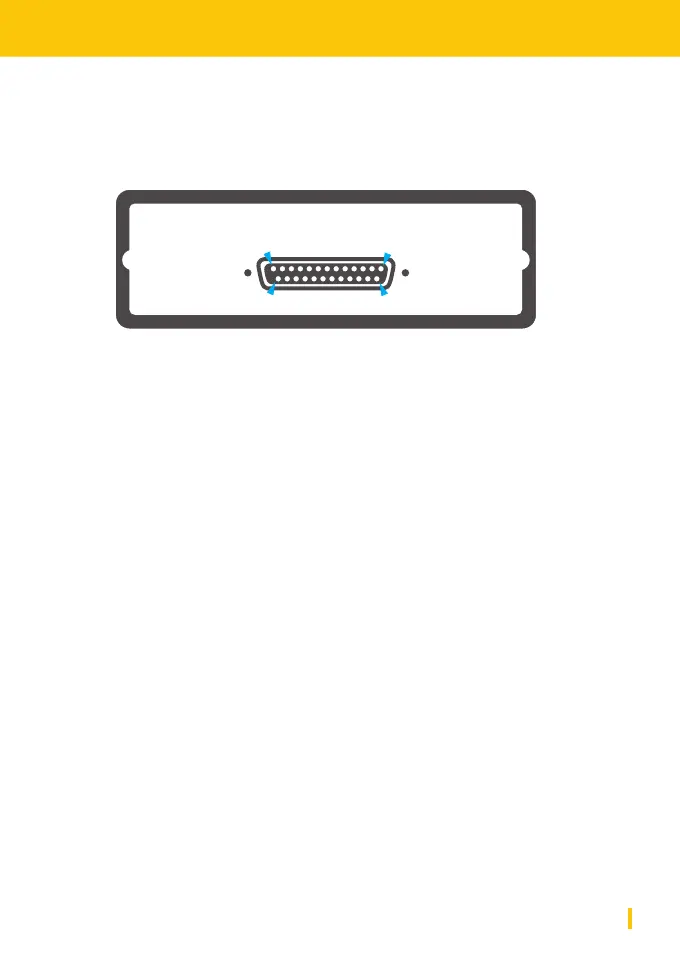
PUC2 Multipin Rear Panel
D-Typ
The rear panel of PUC2 Multipin
provides an analog D-Type pin
connector. It features the same
pin-out as PUC Classic.
D-Type Connector Pin Layout
Digital Audio Input Sub-D
Standard: s/PDIF Signal Pin 14
Shield Pin 2
Optional AES/EBU Signal+ Pin 14
Signal- Pin 2
Shield Pin 15
Digital Audio Ouput Sub-D
Standard: S/PDIF Signal Pin 3
Shield Pin 16
Optional: AES/EBU Signal+ Pin 3
Signal- Pin 16
Shield Pin 15
Analog Audio Input Sub-D
Left Channel Signal+ Pin 25
Signal- Pin 13
Shield Pin 12
Right Channel Signal+ Pin 24
Signal- Pin 11
Shield Pin 12
Analog Audio Ouput Sub-D
Left Channel Signal+ Pin 9
Signal- Pin 21
Shield Pin 22
Right Channel Signal+ Pin 10
Signal- Pin 23
Shield Pin 22
GPI Sub-D
ZLM Zero Latency Mon. Pin 18
BYPASS Dig. Bypass Pin 17
INT LVL International Level Pin 5
AUX Power Out Sub-D
digital +5V/max.40mA Pin 6
digital 0V Pin 19
analog +15V/max.10mA Pin 20
analog -15V/max.10mA Pin 7
analog OV Pin 8
113
1425
*
*Note that if this model is used, the AES input of the front panel is disabled.