Related
Accessories
Related
Accessories
8
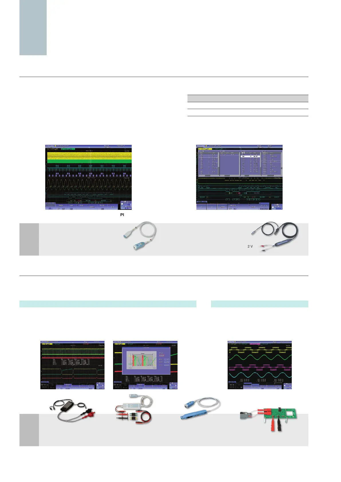
Serial analysis function options (/F1 to /F11)
—UART (RS232)/I
2
C/SPI/CAN/CAN FD/LIN/FlexRay/SENT/PSI5/CXPI—
Triggers for embedded systems and in-vehicle bus signals are supported along
with decode display analysis (serial bus analysis option only on 4 ch models.
Trigger functions of some of the serial buses are not supported). Logic input
can also be used for specic serial buses (UART, I
2
C, SPI, SENT).
Intelligent serial bus auto setup: Complicated trigger and decode settings
such as bit rate and threshold level are automatically detected by DLM2000.
Simultaneous analyses of four different busses: Up to four busses can be analyzed simultaneously. Waveforms and analysis results from
busses with different speeds can be displayed using 2 Zoom windows.
Power supply analysis option (/G3, /G4)
Dedicated power supply analysis options are available (4 ch models only) for switching loss, joule integral (I
2
t), SOA (safe operating area)
analysis, harmonic analysis of power supply current based on EN61000-3-2, and other power parameter measurement such as active power,
power factor etc.
Inputs supported for serial bus analysis
I
2
C SPI
UART
LIN CAN
CAN FD FlexRay
SENT PSI5 CXPI
Analog input
Yes Yes Yes Yes Yes Yes Yes Yes Yes Yes
Logic input
Yes Yes Yes NA NA NA NA Yes NA NA
Simultaneous analyses of I
2
C and SPI
Four bus decode and list display
PBDH1000 differential probe (701924)
1.0 GHz bandwidth
1 MΩ, approximately 1.1 pF
Maximum differential input voltage range: ±25 V
Differential probe
(701926)
DC to 50 MHz
5000 Vrms/7000 Vpeak
PBDH0150 Differential
probe (701927)
DC to 150 MHz
1000 Vrms/ ±1400 Vpeak
PBC100/PBC050 Current
probe (701928/701929)
DC to 100 MHz (701928)
DC to 50 MHz (701929)
30 Arms
Deskew correction
signal source (701936)
Differential probe (701920)
DC to 500 MHz bandwidth
100 kΩ, approximately 2.5 pF
Maximum differential input voltage range: ±12 V
Switching loss analysis
Utilizing the long memory capability, voltage and current waveforms over long cycles
can be input for computation of switching loss (V(t) × i(t)).
A wide variety of switching loss analyses are supported, including turn-on/off loss
calculation, loss including continuity loss, and loss over long cycles of 50 Hz/60 Hz
power line.
Power parameter measurement
Automated measurement of power parameters
for up to two pairs of voltage and current
waveforms, such as active power, apparent
power, power factor etc. Values can be
statistically processed and caluculated.
pecialty
Analysis option for application
S

 Loading...


