9
Software Control http://tmi.yokogawa.com/ea/products/oscilloscopes/oscilloscopes-application-software/
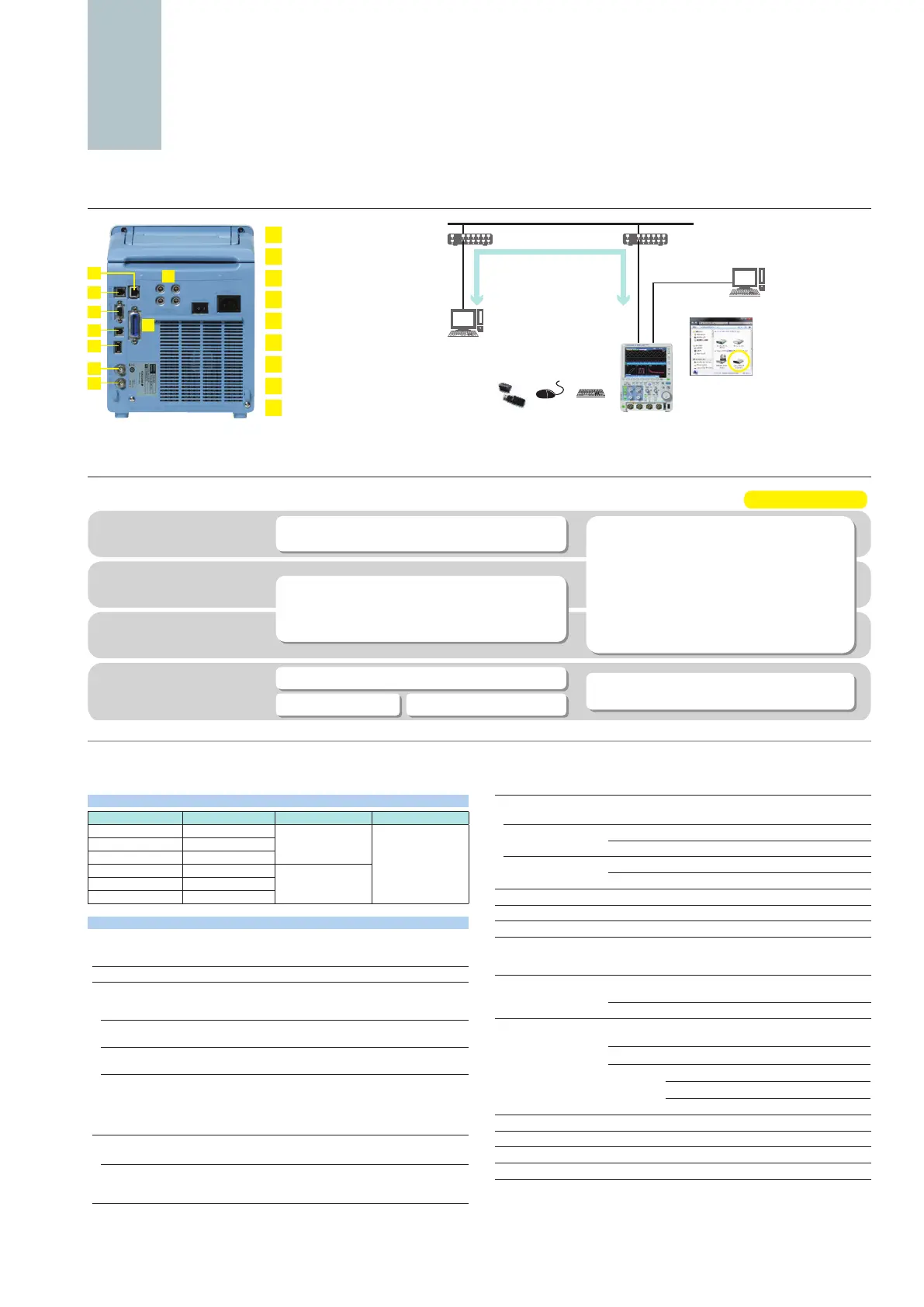
Broad Connectivity and Easier Control
1
Ethernet (optional)
2
GO/NO-GO output terminal
3
RGB video signal output terminal
4
USB-PC connection terminal
5
USB peripheral connection terminal
6
External trigger input
7
Trigger output
8
GP-IB connection terminal (optional)
9
Probe power terminal (optional)
2
3
4
6
5
7
1
8
9
onnectivity
Wide range of interface and software
C
On PCs
DLM2000’s internal
storage can be
recognized by a PC as an
external USB storage
device. Transferring les
is easy even when a USB
thumb drive can’t be used.
1000BASE-T/100BASE-TX/10BASE-T
compliant adapters
(hubs and routers)
and settings data
Remote control
Sends waveform, screen,
and settings data
Remote control
Mail transmission
(GO/NO-GO action)
USB
(standard on rear panel)
Ethernet
(/C10, /C11 options)
Supports USB storage,
USB mouse and keyboard.
mouse keyboad
Free Software Optional Software
Off-line waveform
display and analysis
Waveform monitoring
on a PC
Command control
Custom software
development
Data transfer to a PC
Trial version available
MATLAB Tool Kit
Remote control from MATLAB and data le importing.
XviewerLITE –Basic check–
Zoom, V-cursor, conversion to CSV format
Control library “TMCTL” For Visual Studio
DL-Term
Interactive tool
LabVIEW instrument driver
XWirepuller
Remote monitor and operation
Transferring image les
Xviewer –Advanced Analysis–
Advanced and useful functions are supported.
Good for precise, off-line waveform analysis.
• Waveform observation and analysis
• Cursor, Parameteric Measure
• Statistical Analysis
• Multiple le display
• Advanced waveform operations
• Comment, marking, printing and making report
• Optional Math computation feature
• Remote monitor
• Instruments communication function
• Transferring waveform & image les
Main Specication
Models
Model name
Frequency bandwidth
Input terminal Max. sample rate
DLM2022 (710105) 200 MHz
2 analog channels
1.25 GS/s
(interleave mode off)
2.5 GS/s
(interleave mode on)
DLM2032 (710115) 350 MHz
DLM2052 (710125) 500 MHz
DLM2024 (710110) 200 MHz
4 analog channels or
3 analog channels
+ 8 bit logic
DLM2034 (710120) 350 MHz
DLM2054 (710130) 500 MHz
Analog Signal input
Input channels
Analog input DLM20x2: CH1, CH2
DLM20x4: CH1 to CH4 (CH1 to CH3 when using logic input)
Input coupling setting AC, DC, DC50 Ω, GND
Input impedance
Analog input 1 MΩ ±1.0%, approximately 20 pF
50 Ω ±1.0% (VSWR 1.4 or less, DC to 500 MHz)
Voltage axis sensitivity
setting range
1 MΩ 2 mV/div to 10 V/div (steps of 1-2-5)
50 Ω 2 mV/div to 500 mV/div (steps of 1-2-5)
Max. input voltage 1 MΩ 150 Vrms
50 Ω Must not exceed 5 Vrms or 10 Vpeak
Max. DC offset setting
range
1 MΩ 2 mV/div to 50 mV/div ±1 V
100 mV/div to 500 mV/div ±10 V
1 V/div to 10 V/div ±100 V
50 Ω 2 mV/div to 50 mV/div ±1 V
100 mV/div to 500 mV/div ±5 V
Vertical-axis (voltage-axis)
DC accuracy
*1
±(1.5% of 8 div + offset voltage accuracy)
Offset voltage accuracy
*1
2 mV to 50 mV/div ±(1% of setting + 0.2 mV)
100 mV to 500 mV/div ±(1% of setting + 2 mV)
1 V to 10 V/div ±(1% of setting + 20 mV)
Frequency characteristics (−3 dB attenuation when inputting a sinewave of amplitude ±3div)
*1*2
DLM202x DLM203x DLM205x
1 MΩ (when using
passive probe)
100 mV to 100 V/div 200 MHz 350 MHz 500 MHz
20 mV to 50 mV/div 150 MHz 300 MHz 400 MHz
50 Ω 10 mV to 500 mV/div 200 MHz 350 MHz 500 MHz
2 mV to 5 mV/div 150 MHz 300 MHz 400 MHz
Isolation between channels Maximum bandwidth: −34 dB (typical value)
Residual noise level
*3
The larger of 0.4 mV rms or 0.05 div rms (typical value)
A/D resolution 8 bit (25 LSB/div) Max. 12 bit (in High Resolution mode)
Bandwidth limit FULL, 200 MHz, 100 MHz, 20 MHz, 10 MHz, 5 MHz, 2 MHz,
1 MHz, 500 kHz, 250 kHz, 125 kHz, 62.5 kHz, 32 kHz, 16 kHz,
8 kHz (can be set for each channel)
Maximum sample rate Real time sampling mode Interleave OFF 1.25 GS/s
Interleave ON 2.5 GS/s
Repetitive sampling mode 125 GS/s
Maximum record length (Points)
Repeat Single Single Interleave
2 ch model /M1S 6.25 M 25 M 62.5 M
4 ch model /M1 6.25 M 25 M 62.5 M
/M2 12.5 M 62.5 M 125 M
/M3 25 M 125 M 250 M
Ch-to-Ch deskew ±100 ns
Time axis setting range 1 ns/div to 500 s/div (steps of 1-2-5)
Time base accuracy
*1
±0.002%
Max. acquisition rate
*4
Approx. 20000 waveform/sec/ch (Accumulation mode)
Dead time in N Single mode Approx. 2.2 µs (approx. 450000 waveforms/sec/ch)

 Loading...


