4-71
IM DLM3054-01EN
Level (Level), HF Rejection (HF Rejection), Noise Rejection (Noise Rejection)*
Set these items for Clock, Data1, Data2, and CS.
These items are the same as those of the edge trigger.*
* You can set this only when the trigger source is set to LOGIC and the 701989 logic probe is connected.
Hysteresis (Hysteresis)
You can set this only when the trigger source is CH1 to CH4.
This item is the same as that of the CAN bus trigger.
Trigger Point
The trigger point is determined by the clock polarity setting as follows:
Polarity: Trigger point when
the polarity is set
Clock
or
Polarity: Trigger point when
the polarity is set
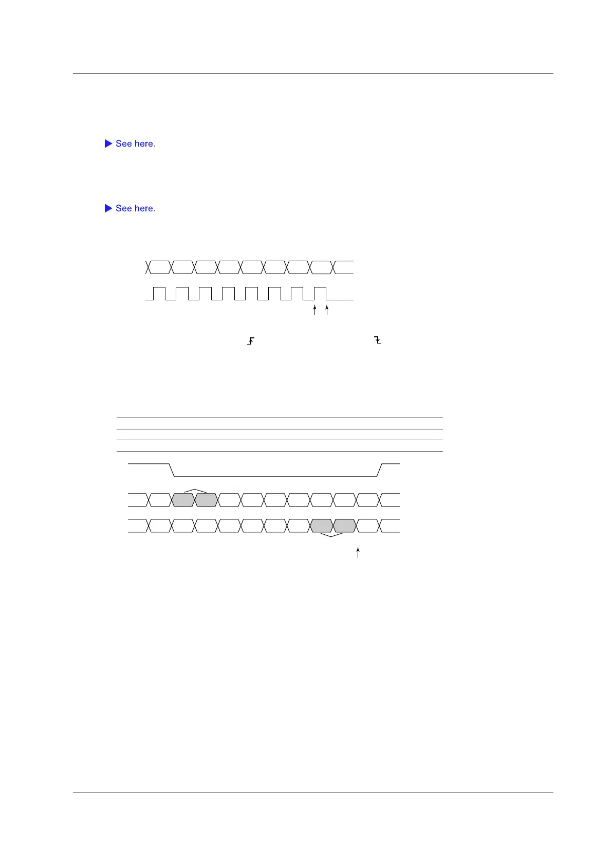
Example
This example displays the data sequence in hexadecimal (Hex) notation and indicates the trigger position.
The Data1 and Data2 pattern references are set to A1 and A2, respectively.
Shading: Pattern to compare
CS Active: L
Data 1 Condition: True, Position: 0, Size: 2 bytes, Data pattern: A4 and 25
Data 2 Condition: True, Position: 6, Size: 2 bytes, Data pattern: 85 and C8
11 A4 25 EA 57 FF 68 00 00 00
00 00 00 00 00 00 00 85 C8 22
Matches Data 1
Matches Data 2
0 1 2 3 4 5 6 (Data Position)
4 Triggering

 Loading...


