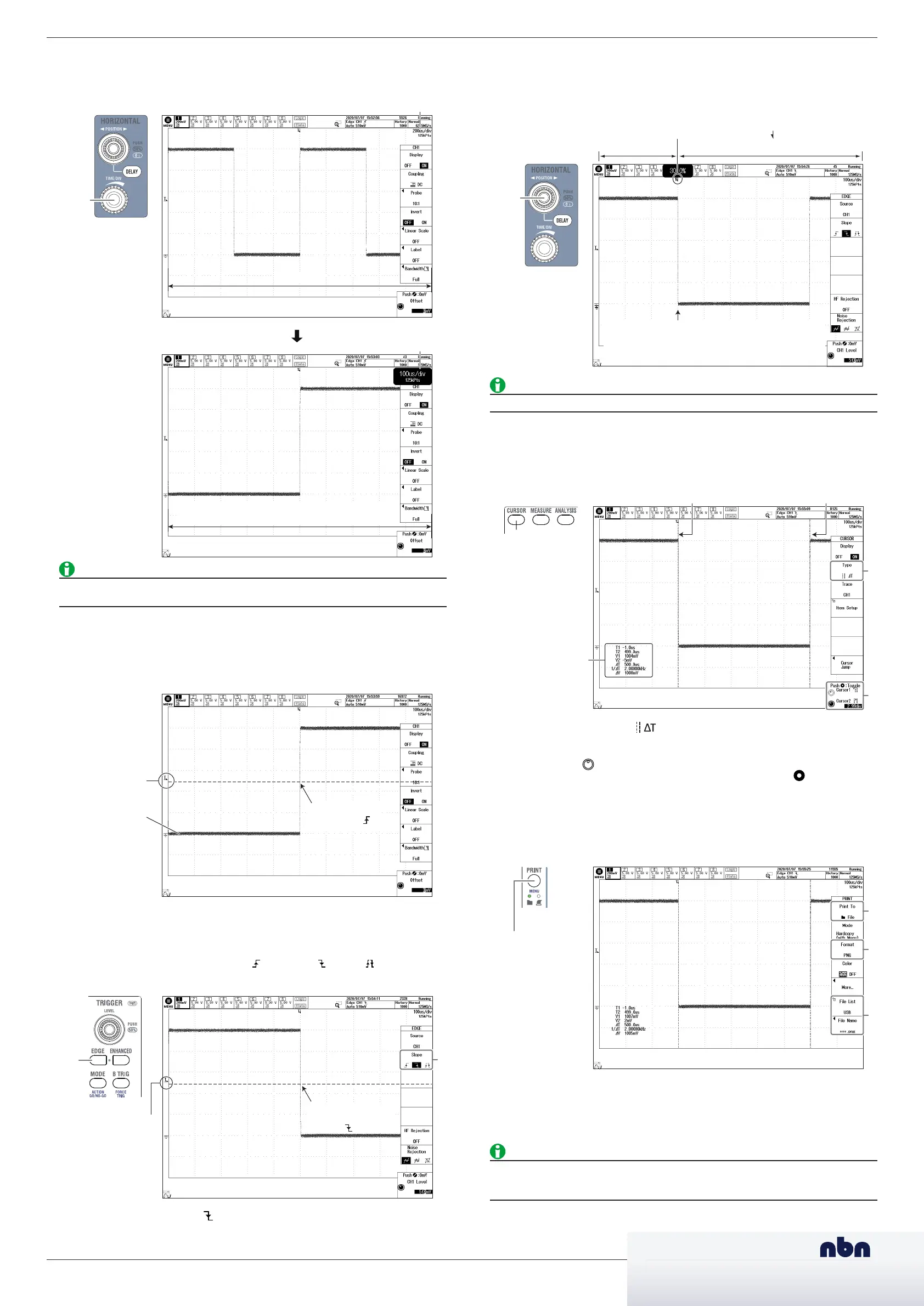
Changing the Trigger Position from 50% (screen center) to 30%
When you start waveform acquisition, the instrument triggers according to the specified conditions
and displays the waveform captured in the acquisition memory. You can move the trigger position
on the screen to change the display ratio of the data previous to the trigger point (pre-trigger
section) and the data after the trigger position (post-trigger section).
1.
Use the POSITION to move the trigger position to the left by 2 divisions. The trigger position is
set to 30%.
Set the trigger position ( ) to 30%.
Post-trigger section
The waveform moves to the left causing more of the
waveform after the trigger (post-trigger section) to
be seen.
Pre-trigger
section
For details on triggers, see chapter 4, “Trigger,” in the Features Guide (IM DLM5058-01EN).
Measuring the Waveform
Use vertical cursors (ΔT cursors) to measure the time and voltage of the displayed waveform.
1.
Press CURSOR.
1
2
Measured values
2.
Press the Type soft key to select (ΔT cursor).
Two vertical cursors, the times (T1, T2) and voltages (V1, V2) at the cursor positions, and other
measurements are displayed.
3.
Turn the jog shuttle (
) to move a cursor.
The cursor that the jog shuttle controls switches each time you press SET ( ). You can also
select both T cursor 1 and T cursor 2.
Saving the Waveform Screen Image
You can save screen captures. The available data formats are PNG, BMP, and JPEG.
1.
Press SHIFT + PRINT.
(SHIFT + PRINT)
(PRINT)
2.
Press the Print To soft key to set the output destination to File.
3.
Use the Format soft key to set or view the data format, the File List soft key to set or view the
save destination, and the File Name soft key to set or view the file name.
4.
Press PRINT. A screen capture is saved.
• For details on saving screen captures, see chapter 16.5, “Saving Screen Captures to Files,” in
the User’s Manual (IM DLM5058-02EN).
• To use the built-in printer (option), change Print To to BuiltIn.
Changing the Horizontal Axis Settings
Change the horizontal (time) scale from 200 µs/div to 100 µs/div. Setting the time scale means setting
the time per grid division.
1.
Use the TIME/DIV knob to change Time/div to 100 µs/div.
10 div = 2 ms
Time/div: 100 µs/div
10 div = 1 ms
(the waveform is expanded horizontally)
For details on the horizontal axis, see chapter 3, “Horizontal Axis (Time Axis),” in the Features
Guide (IM DLM5058-01EN).
Changing the Edge Trigger Settings
Edge triggers are simple triggers that are activated when the trigger source passes through a trigger
level. A change in the waveform that causes it to pass through a trigger level is called an edge.
When you execute auto setup, the edge trigger is automatically set.
Trigger level
Triggers here
(rising edge ( ))
Here, change trigger slope and trigger position settings of the edge trigger.
Changing the Trigger Slope from Rising to Falling
Use the slope to set the direction of the edge. There are two edge directions: rising (movement from
a low level to a high level) and falling (movement from a high level to a low level). Setting the slope
allows triggers to be activated on the rising edge ( ), falling edge ( ), or both ( ).
1
.
Press EDGE.
Trigger level
Triggers here when
the slope is set to
falling ( ).
2.
Press the Slope soft key to select (falling). The instrument will trigger on the falling edges of
the trigger source.
IM DLM5058-04EN 2/2
nbn @ nbn. at
www. nbn. at
Riesstraße 146, 8010 Graz
Tel. +43 316 40 28 05 | Fax +43 316 40 25 06
nbn Austria GmbH

 Loading...


