15
IM 04L55B01-02EN
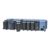
In wall mounting, the GM90PS is the reference.
First, as shown in the figure below, fix the GM90PS
securely in place with two screws. Next, link GM90MBs to
the GM90PS.
Screw
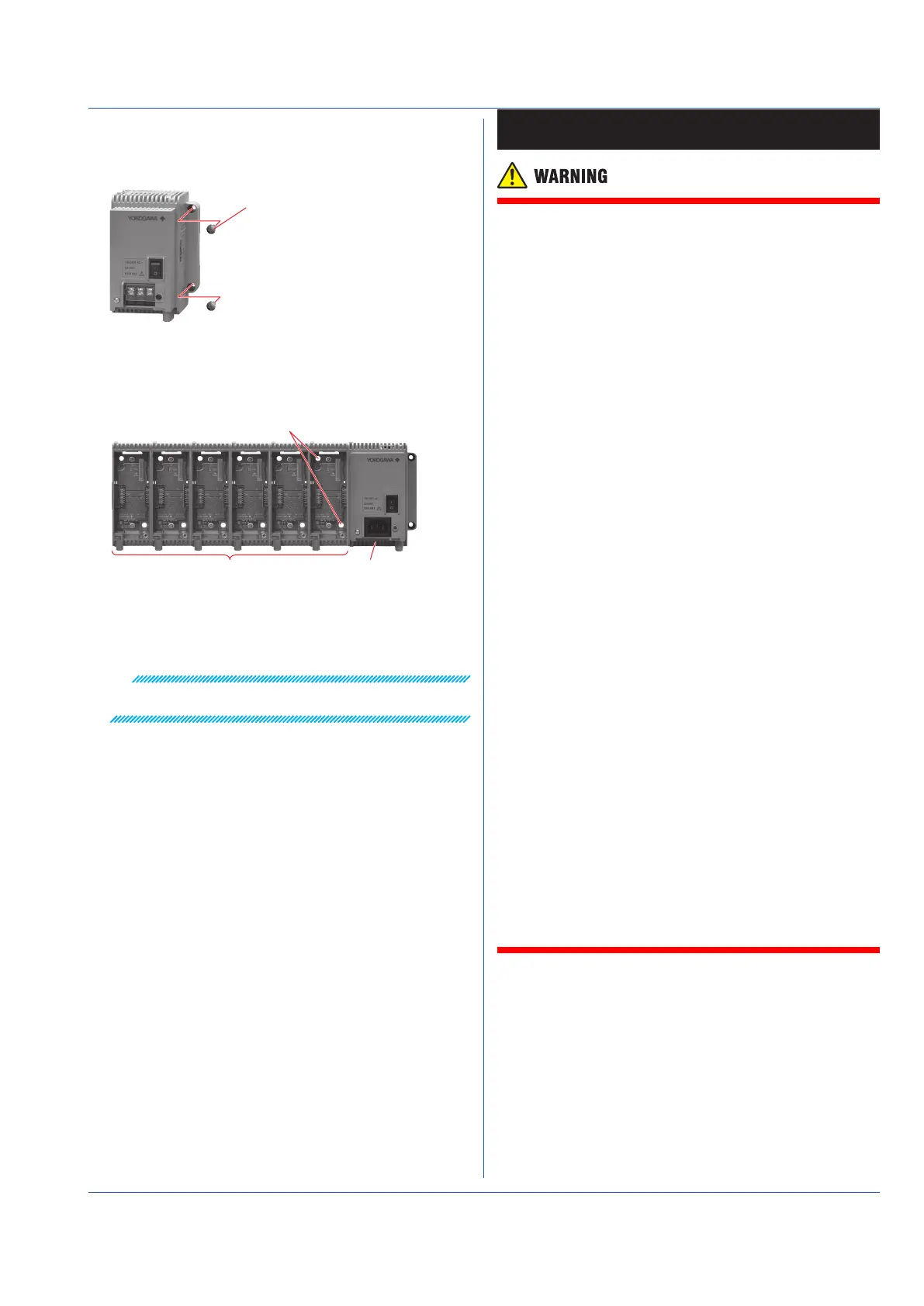
Link GM90MBs to the right of the GM90PS as seen
from the front. While pressing the GM90MB against the
GM90PS, fasten in place with screws.
• GM90MBs can be fixed in place one at a time or at once
after they have been linked.
Holes for wall mounting
GM90MB GM90PS
For the linking procedure, see “Operating Procedure” on
page 8 of this guide.
After fixing the GM90MBs in place, install the modules.
Note
Install so that nameplate on the right side of the GM90PS is
visible.
Wiring
● Topreventelectricshockwhilewiring,makesurethat
the power supply is turned off.
● Ifavoltageofmorethan30VACor60VDCistobeap-
plied to the output terminals, use ring-tongue crimp-on
lugs with insulation sleeves on all terminals to prevent
the signal cables from slipping out when the screws
become loose. Furthermore, use double-insulated
cables (dielectric strength of 2300 VAC or more) for the
signal cables on which a voltage of 30 VAC or 60 VDC
or more is to be applied. For all other signal cables,
use basic insulated cables (dielectric strength of 1390
VAC). To prevent electric shock, attach the terminal
cover after wiring and make sure not to touch the ter-
minals.
● Applyingastrongtensiontotheinputandoutput
signal cables connected to the GM may damage the
cables or the GM terminals. To avoid applying tension
directlytotheterminals,xallcablestothemounting
panel.
● Topreventre,usesignalcableswithatemperature
rating of 70°C or more.
● Donotapplyvoltagesthatexceedthefollowingval-
ues to the input terminals. Doing so may damage the
instrument.
GX90XA
• Allowable input voltage:
±10 V DC for TC/DC voltage (1 V range or less)/RTD/DI
(Contact), DC mA
±60 V DC for DC voltage (2 V to 50 V range), DI (volt-
age) input (except High-speed AI)
±120 V DC for DC voltage (2 to 100 V range ) input , DI
(voltage) (Highspeed AI)
• Common mode voltage:
±60 VDC (under measurement category II conditions)
±300 VAC rms (under measurement category II condi-
tions (High-speed AI)
GX90XD and GX90WD
• Allowable input voltage: +10 VDC
GX90XP
• Allowable input voltage: ±10 VDC
GX90UT
• Allowable input voltage: ±10 V DC for TC/DC voltage (1 V
range or less)/ RTD/DI (Contact), DC mA ±60 V DC for
DC voltage (2 V range or more), DI (voltage)
• Common mode voltage: ±60 VDC (under easurement
category II conditions)
● TheGMisaninstallationcategoryIIproduct.
 Loading...