7
IM 04L55B01-02EN
Limit on Modules
・ Upto10modulesconsistingofGX90YD,GX90WD,and
GX90UTcanbeconnectedtothesystem.
・ OneGX90WDmodulecanbeconnectedtoeachunit.
・ TwoGX90YAmodulescanbeconnectedtothemainunit
andtothesubunit.
・ Upto10GX90YAmodulescanbeconnectedtoaGM10-1
systemandupto12toaGM10-2system.
・ IfthemeasurementmodeisHighspeed,aGX90XDor
GX90WDmodulecanbeconnectedtothesystem.
・ IfthemeasurementmodeisHighspeed,onlyGX90XA-
04-H0(high-speedAI),GX90XD(DI),andGX90WD(DIO)
aredetected.DIandDIOarefixedtoremotemode.
Measurementandrecordingarenotpossible.
・ IfthemeasurementmodeisDualinterval,GX90UTisnot
detected.
・ Upto3GX90UTmodulescanbeconnectedtoaGM10-1
systemandupto10toaGM20-2system.
Notes on Module Installation
• Ifyouwanttousereferencejunctioncompensationona
thermocoupleinputofaGX90XA-10-U2,GX90XA-10-L1,
orGX90XA-10-T1,donotconnectthefollowingmoduleto
therightoftheGX90XAmoduleasseenfromthefront.
Doingsomaycausethereferencejunctioncompensation
accuracytodeviatefromtheguaranteedrange.
GX90XA-10-C1(formA),GX90XA-04-H0(high-speedAI),
GX90YA,GX90WD,GX90UT
•IfthemaximumnumberofI/Ochannelsareassignedand
thelastchannelisassignedtoanintermediatechannel
ofaconnectedI/Omodule,thatmoduleandsubsequent
moduleswillnotbeidentified.
• • •
1
10
:
81
90
:
91
100
106
:
:
Maximum
number of I/O
channels
This module will not be detected.
GM10-1
• If you want to use the DI of a GX90XD or GX90WD, only a
single module installed in the GM main unit can be used.
• Do not link modules in a way that violates the
specifications. Doing so can cause the GM system to
crash. For details on the ways modules could be linked to
crash the GM system, see the User’s Manual.
Limitations depending on the Measurement Mode
Depending on the measurement mode, there are limits
to the number of measurement channels, the number of
recording channels, the supported modules, and so on.
For the specific limitations, see the limitations provided in
the following general specifications.
• GM Data Acquisition System General Specifications
(GS 04L55B01-01EN)
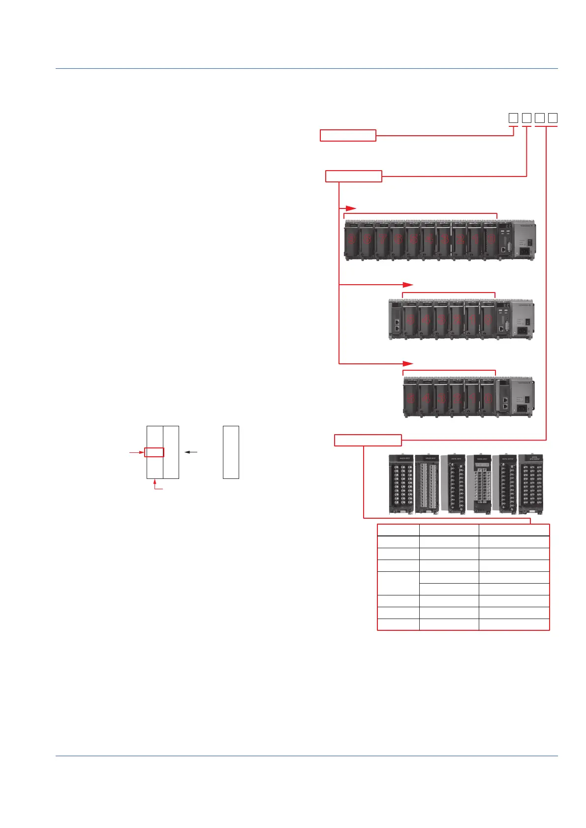
Channel Names
Operations such as measurement, computation, and
recording are performed on channels.
A channel name is assigned a 4-digit number consisting of a
unit number, slot number, and channel number.
• Channel names are specific to the system, so they cannot
be changed.
• By setting tags or tag numbers to the channels, you can
use any names you like.
Unit number
Slot number
Channel number
I/O module
Main Unit (single unit system)
Main unit: 0
Sub unit: 1 to 6
0 to 9
Main unit (multi unit system)
Sub unit (multi unit system)
0123456
012345
012345
789
GX90XA
GX90XD
GX90YD
GX90WD
GX90XP
GX90YA
Analog input
Digital input
Digital output
Digital input
Digital output
Pulse input
Analog output
01 to 10
01 to 16
01 to 06
01 to 08
09 to 14
01 to 10
01 to 10
Model I/O Channel number
0 to 5
0 to 5
Example: If 10 GX90XAs are linked to the main unit (single
unit system), the channel name of channel 3 of slot 5 is
“0503.”
 Loading...