22
IM 04L55B01-02EN
Wiring the Power Supply
Use a power supply that meets the following conditions:
Item Condition
Rated supply voltage 100 to 240 VAC ± 10%
Allowable power supply voltage
range
90 to 264 VAC
Rated power supply frequency 50/60Hz
Permitted power supply
frequency range
50/60Hz ± 2%
Power
consumption
Supply voltage
100V AC
25 VA (normal
operation*)
45 VA
(maximum)
Supply voltage
240V AC
35 VA (normal
operation*)
60 VA
(maximum)
* When 10 GX90XA-10-U2 are connected
Note
• Do not use a supply voltage of 132 to 180 VAC, as this
may have adverse effects on the measuring accuracy.
Notes on the Functional Ground Terminal
• To reduce noise, use a shielded cable for wiring. Connect
the shield to the functional ground terminal or the ground
terminal of the GM.
• Do not wire the protective grounding cord to the functional
ground terminal.
Functional
ground terminal
Precautions to Be Taken While Wiring the Power
Supply (power supply M4 screw terminals)
Make sure to follow the warnings below when wiring the
power supply. Failure to do so may cause electric shock or
damage to the instrument.
● Topreventelectricshock,ensurethatthepowersup-
ply is turned off.
● Topreventre,use600VPVCinsulatedwires(AWG20
to AWG16; JIS C3307) or wires or cables with equiva-
lent or better performance.
● Makesuretoearthgroundtheprotectivegroundter-
minal through minimum resistance before you turn on
the power.
● Usecrimp-onlugs(designedfor4mmscrews)with
insulation sleeves to connect both the power cord and
the protective ground.
● Topreventelectricshock,besuretoclosethetrans-
parent cover for the power supply wires.
● Provideapowerswitch(double-poletype)onthe
power supply line to separate the GM from the main
power supply. Use labels to indicate that this switch
is for cutting off the power supply to the GM and to
indicate ON and OFF.
Switch specifications
Steady-state current rating
3 A or more
Inrush current rating
70 A or more
Must comply with IEC60947-1 and IEC60947-3.
● Donotaddaswitchorfusetothegroundline.
Wiring Procedure
1. Turn off the GM90PS power supply, and then remove the
transparent power supply terminal cover.
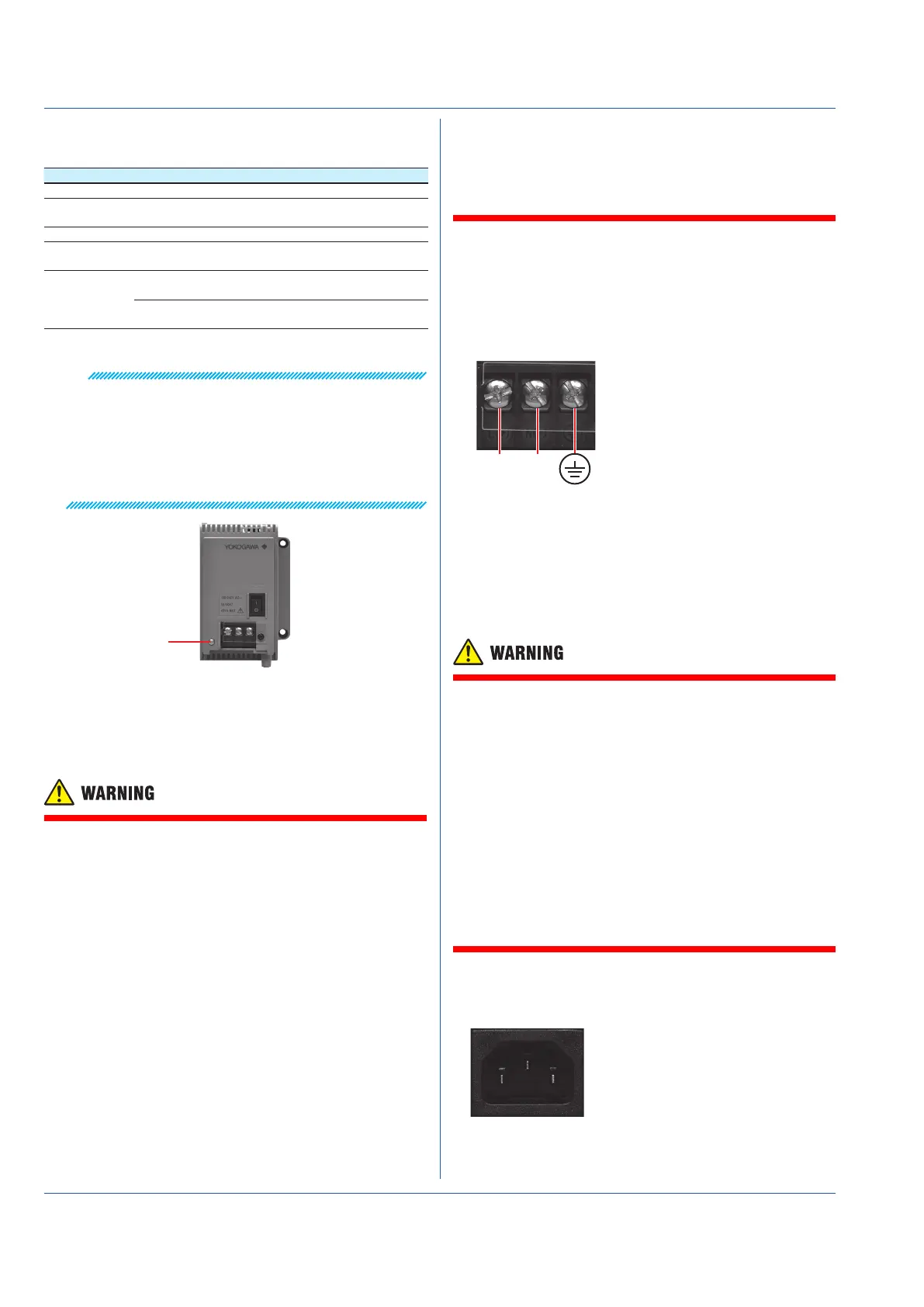
2. Connect the power cord and the protective ground cord to
the power supply terminal. Use ring-tongue crimp-on lugs
(for M4 screws) with insulation sleeves. The recommended
torque for tightening the screws is 1.4 to 1.5 N•m.
Protective ground
L(+) N(−)
3. Attach the transparent power supply terminal cover, and
fasten it with screws.
Precautions to Be Taken When Connecting the
Power Supply (Power inlet)
Make sure to follow the warnings below when connecting the
power supply. Failure to do so may cause electric shock or
damage to the instrument.
● Beforeconnectingthepowercord,ensurethatthe
source voltage matches the rated supply voltage of
the GM90PS and that it is within the maximum rated
voltage range of the provided power cord.
● Connectthepowercordaftercheckingthatthepower
switch of the GM90PS is turned OFF.
● Topreventelectricshockandre,besuretousea
power cord purchased from Yokogawa Electric Corpo-
ration.
● Makesuretoconnectprotectiveearthgroundingto
prevent electric shock. Insert the power cord into a
grounded three-prong outlet.
● Donotuseanextensioncordwithoutaprotective
earth ground. If you do, the instrument will not be
grounded.
Connection Procedure
1. Check that the GM90PS power switch is off.
2. Connect the supplied power cord plug to the power inlet.

 Loading...