23
IM 04L55B01-02EN
3. Make that the source voltage is within the maximum rated
voltage range of the provided power cord. Then, connect
the other end of the cord to the outlet. Use a grounded
three-prong outlet.
Precautions to Be Taken While Wiring the Power
Supply (Power Supply Suffix Code: 2)
Make sure to follow the warnings below when wiring the
power supply. Failure to do so may cause electric shock or
damage to the instrument.
● Wirethepowercabletothepowersupplyterminal,
making sure that the polarity is correct.
● Connectthepowercablesaftercheckingthatthe
power switch of the GM90PS is turned OFF.
● Usingotherwiresmaycauseabnormalheatingorre.
Wiring Procedure
1. Turn off the GM90PS power supply, and then remove the
transparent power supply terminal cover.
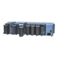
2. Wire the power cable to the power supply terminal, making
sure that the polarity is correct.
Use ring-tongue crimp-on lugs (for M4 screws) with
insulation sleeves. The recommended torque for tightening
the screws is 1.4 to 1.5 N•m.
+ −
3. Attach the transparent power supply terminal cover, and
fasten it with screws.
Turning the Power On and Off
If the power switch of GM/GX60 systems under
operation be turned on or off carelessly, it may result
the system down or injury.
Check the following points before turning on the power
switch.
● Thepowercordorwiresareconnectedproperly.
● TheGMisconnectedtothecorrectpowersupply.
If the input wiring is connected in parallel with another
instrument, do not turn on or off the GM or other
instrument during operation. If you do, measured values
may be affected.
Check the following points before turning off the power
switch.
● TheGM10isnotaccessingtheexternalstorageme-
dium.
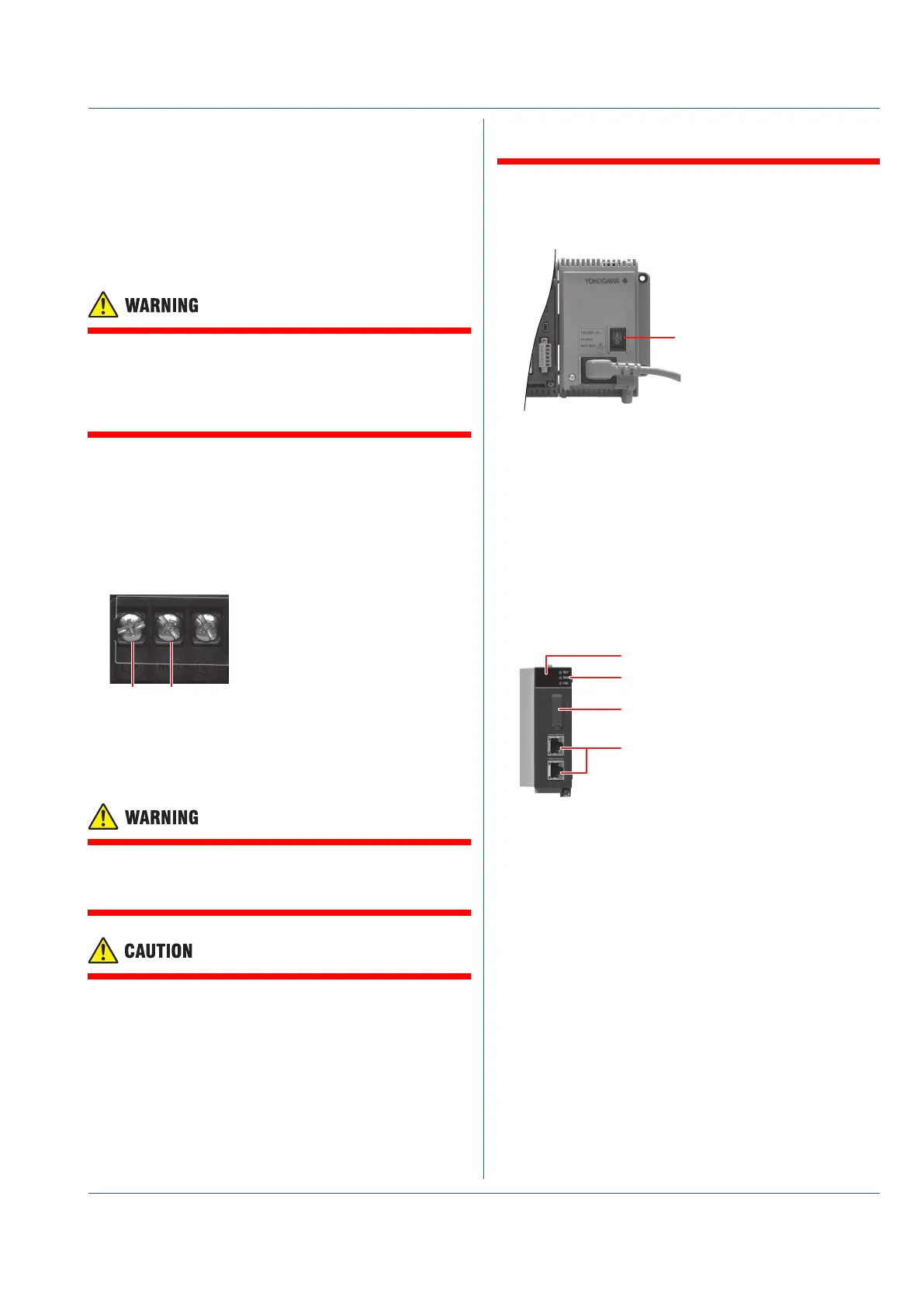
You can turn the power on and off using the power switch
on the front panel of the GM90PS.
A self-test takes place for a few seconds, and then the GM
will be running.
Power switch
Connecting GX90EX Expansion Modules
The GX90EX is used to configure a multi unit system.
• For the main unit, link the GX90EX to the left end as seen
from the front of the unit.
• For a sub unit, link it next to the GM90PS.
Connect the GX90EXs of the main unit and sub units with
Ethernet STP (shielded) cables. Only cascaded connection is
supported.
Configuring the GX90EX Expansion Modules
Before setting the GX90EX dipswitches, turn off the unit.
Port
Setting switches (dipswitches)
System status LED
EXBus status LED
7 segment LED
 Loading...