17
IM 04L55B01-02EN
Wiring Procedure
A terminal cover is screwed in place on the I/O terminal block.
A label indicating the terminal arrangement is affixed to the
cover.
1.
Turn off the power, and remove the terminal cover.
2. Connect the signal cables to the terminals.
Recommended
torque for
tightening the
screws
Screw terminal (M3) 0.5 to 0.6 N•m
Clamp terminal GX90XA: 0.4N•m
GX90XP: 0.4N•m
GX90XD: 0.5N•m
3. Replace the terminal cover and fasten it with screws. The
recommended tightening torque for the screws is 0.6 N•m.
Note
With a clamp terminal, if you use a single wire whose
diameter is 0.3 mm or less, you may not be able to clamp
the wire securely to the terminal. Take measures to securely
clamp the wire such as by folding the conductor section that
will be connected to the clamp terminal in half.
Internal dimensions of the M3 screw
terminal (unit: mm)
6
0
−0.1
Wiring the Clamp Terminal
Flat blade
Screw
terminal
Connection
port
First, loosen the front screw
terminal using a flat-blade
screwdriver.
Insert a wire in the connection
port, and tighten the screw
terminal.
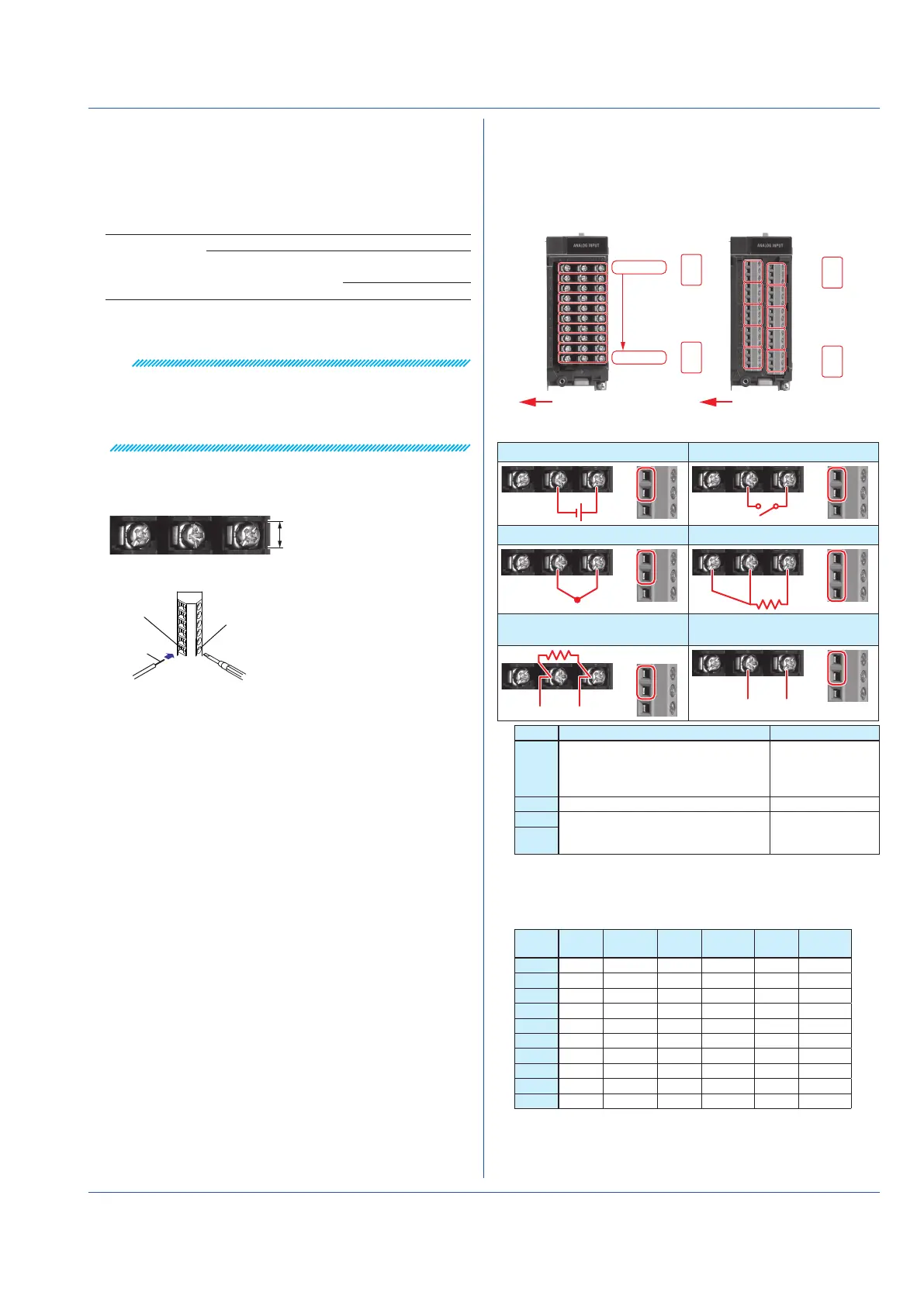
Wiring to a GX90XA Analog Input Module
Universal / Low withstand voltage relay /
Electromagnetic relay / Current (mA) type
Terminal Diagram
CH1
301/201/101
101
102
103
113
114
115
310/210/110
M3 screw terminal
Clamp terminal
Wiring direction
CH10
201
202
203
213
214
215
CH1
CH3
CH5
CH7
CH9
CH2
CH4
CH6
CH8
CH10
Wiring Diagram
1: DC voltage input/DI (level) 2: DI (contact)
+−
−
3: TC input 4: RTD input
+−
−
B
b
ABb
5: DC current input (with an
external shunt resistor)
6: Current input
+−
−
+
−
Type Input type Wiring
-U2 DC voltage, DI, thermocouple (TC),
Resistance temperature detector
(RTD), and DC current (by adding an
external shunt resistor)
1, 2, 3, 4, 5
-C1 DC current (mA) 6
-L1 DC voltage, thermocouple (TC), DI
(voltage, contact), and DC current (by
adding an external shunt resistor)
1, 2, 3, 5
-T1
Terminal Arrangement
M3 screw terminal
CH
No.
Term.
No.
Symbol Term.
No.
Symbol Term.
No.
Symbol
CH1 301 b
1
201 -/B 101 +/A
CH2 302 b
1
202 -/B 102 +/A
CH3 303 b
1
203 -/B 103 +/A
CH4 304 b
1
204 -/B 104 +/A
CH5 305 b
1
205 -/B 105 +/A
CH6 306 b
1
206 -/B 106 +/A
CH7 307 b
1
207 -/B 107 +/A
CH8 308 b
1
208 -/B 108 +/A
CH9 309 b
1
209 -/B 109 +/A
CH10 310 b
1
210 -/B 110 +/A
1 There are no symbol indications for the electromagnetic
relay type, current input type, or low withstand voltage
relay type.
 Loading...