2-10
<Toc> <2. Initial Settings>
IM 05F01D02-41E 1st Edition : May 31,2000-00
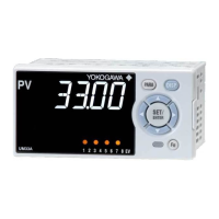
8.
Press the
SET/ENT
key once to register the
setpoint.
PV
AL1234
SET/ENT
You can take the same steps for alarm-2
type (AL2), alarm-3 type (AL3), and alarm-4
type (AL4) that are displayed after this.
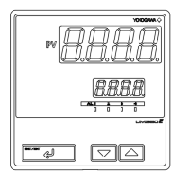
9.
Press the
SET/ENT
key for more than 3 sec-
onds. This returns you to the display
shown at power-on (figure below).
PV
AL1234
SET/ENT
Displays PV.
See “3.2 Setting Alarm Setpoints” when
setting an alarm setpoint.
■ List of Alarm Types
The table below shows the alarm types and alarm actions.
In the table, codes 1, 2, 9, and 10 are not provided with stand-by actions, while codes 11,
12, 19, and 20 are provided with stand-by actions.
Alarm action
Alarm action
Alarm type codeAlarm type code
Alarm type
“Open/close” shows status of relay contact,
and “lit” and “unlit” shows status of lamp
Contact
closes
if alarm
occurs
Contact
opens
if alarm
occurs
Contact
closes
if alarm
occurs
Contact
opens
if alarm
occurs
Alarm type
No alarm OFF
PV high limit
PV low limit
1
11
2
12
De-energized
on PV high limit
De-energized
on PV low limit
9
19
10
20
2221
“Open/close” shows status of relay contact,
and “lit” and “unlit” shows status of lamp
Fault diagnosis output (Note 1) FAIL output (Note 2)
Alarm setpoint
Closed (lit)
Hysteresis
PV
Open (unlit)
Closed (lit)
Hysteresis
Open (unlit)
Alarm setpoint PV
PV
Open (lit)
Alarm setpoint
Hysteresis
Closed
(unlit)
Alarm setpoint
Hysteresis
PV
Open (lit)
Closed
(unlit)
Note 1: Fault diagnosis output
Turns on in case of input burnout, A/D converter failure, or reference junction compensation (RJC) failure.
Note 2: FAIL output
Turns off in case of program failure, ROM failure, RAM failure, or power failure. This output is on during normal
operation.
If it turns off, the retransmission output is set to 0%, the alarm output is set to OFF, and the indicator stops.
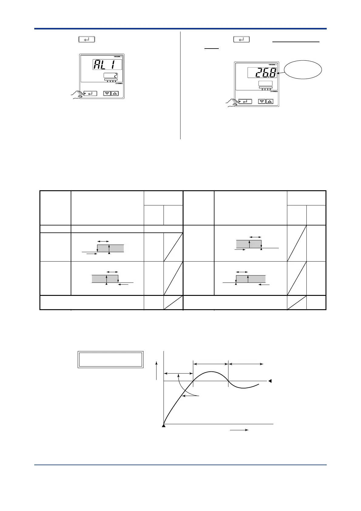
Treated
as normal
⬚C
Power-on
Time
The alarm output does not
turn on in this region even
if the PV value is below the
low limit of the alarm setpoint.
Low limit of
alarm setpoint
Normal Abnormal
The alarm
output turns on.
Stand-by Action

 Loading...