<Toc> <2. Initial Settings>
2-11
IM 05F01D02-41E 1st Edition : May 31,2000-00
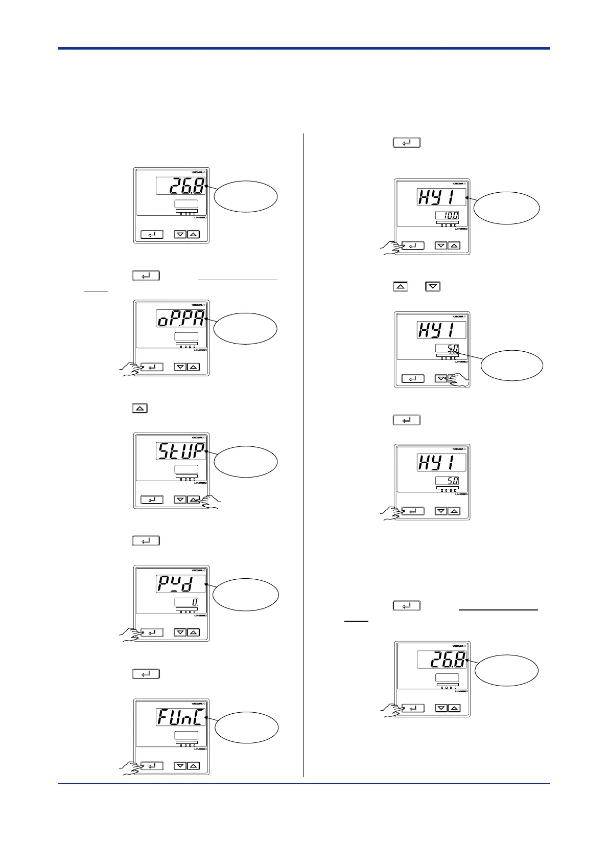
2.5 Setting Hysteresis in Alarm Setpoint
The following operating procedure describes an example of setting a 5.0°C hysteresis level
in the alarm setpoint.
1.
Bring the operating display into view
(appears at power-on).
PV
AL1234
SET/ENT
Displays PV.
2.
Press the
SET/ENT
key for more than 3 sec-
onds to call up the menu “OP.PA”.
PV
AL1234
SET/ENT
Displays
menu “OP.PA”.
3.
Press the key once to display the
menu “STUP”.
PV
AL1234
SET/ENT
Displays
menu “STUP”.
4.
Press the
SET/ENT
key once to display the
parameter “PWD”.
PV
AL1234
SET/ENT
Displays
parameter
“PWD”.
5.
Press the
SET/ENT
key once to display the
menu “FUNC”.
PV
AL1234
SET/ENT
Displays
menu “FUNC”.
6.
Press the
SET/ENT
key several times to
display the parameter “HY1” (alarm-1
hysteresis).
PV
AL1234
SET/ENT
Displays
parameter
“HY1”.
7.
Press the or key to display the
required setpoint.
PV
AL1234
SET/ENT
Blinks during
change.
8.
Press the
SET/ENT
key once to register the
setpoint.
PV
AL1234
SET/ENT
You can take the same steps for alarm-2
hysteresis (HY2), alarm-3 hysteresis (HY3),
and alarm-4 hysteresis (HY4) that are
displayed after this.
9.
Press the
SET/ENT
key for more than 3 sec-
onds. This returns you to the display
shown at power-on (figure below).
PV
AL1234
SET/ENT
Displays PV.

 Loading...