IM 05P03D21-11EN page 1/8
Contents
1. Safety Precautions
2. ModelandSufxCodes
3. How to Install
4. HardwareSpecications
5. HowtoConnectWires
6. TerminalWiringDiagrams
Introduction
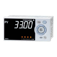
ThankyouforpurchasingtheUM33ADigitalIndicatorwithAlarms.
ThisoperationguidedescribesthebasicoperationsoftheUM33A.Theguideshould
beprovidedtotheenduserofthisproduct.
Be sure to readthis operationguidebeforeusingthe productinordertoensure
correct operation.
Fordetailsofeachfunction,refertotheelectronicmanual.Beforeusingtheproduct,
refertothetableofModelandSufxCodestomakesurethatthedeliveredproduct
isconsistentwiththemodelandsufxcodesyouordered.Alsomakesurethatthe
followingitemsareincludedinthepackage.
•DigitalIndicatorwithAlarms(themodelyouordered) ............................
x1
• Set of Brackets ........................................................................................
x1
•UnitLabel(L4502VZ) ..............................................................................
x1
•TagLabel(L4502VE)(Onlywhenordered.) ...........................................x1
•OperationGuide(thisdocument) ............................................................x4(A3size)
(InstallationandWiring,InitialSettings,Operations,andParameters)
l
TargetReaders
Thisguideisintendedforthefollowingpersonnel;
• Engineersresponsibleforinstallation,wiring,andmaintenanceoftheequipment.
• Personnelresponsiblefornormaldailyoperationoftheequipment.
1. Safety Precautions
Thefollowingsymbolisusedontheinstrument.Itindicatesthepossibility of injury
to theuseror damageto theinstrument, and signiesthattheusermustreferto
the user’s manualfor specialinstructions. Thesamesymbolis usedinthe user’s
manualonpagesthattheuserneedstoreferto,togetherwiththeterm“WARNING”
or“CAUTION.”
Calls attention to actions or conditions that could cause serious
or fatal injury to the user, and indicates precautions that should be
taken to prevent such occurrences.
Calls attention to actions or conditions that could cause injury to
the user or damage to the instrument or property and indicates pre-
cautions that should be taken to prevent such occurrences.
Theequipmentwhollyprotectedbydoubleinsulationorreinforcedinsulation.
Functionalgroundingterminals
(Donotusethisterminalasaprotectivegroundingterminal).
Note
Identiesimportantinformationrequiredtooperatetheinstrument.
n
Warning and Disclaimer
(1) YOKOGAWAmakesnowarrantiesregardingtheproductexceptthosestatedin
theWARRANTYthatisprovidedseparately.
(2) Theproductisprovidedonan"asis"basis.YOKOGAWAassumesnoliabilityto
anypersonor entityforanylossor damage,directorindirect,arisingfromthe
useoftheproductorfromanyunpredictabledefectoftheproduct.
n
Safety,Protection,andModicationoftheProduct
(1) In order to protect thesystemcontrolledbythis product andthe productitself,
and toensuresafeoperation, observethe safety precautionsdescribed inthe
user’s manual.Useoftheinstrument in amannernotprescribed hereinmay
compromise the product's functions and the protection features inherent in the
device.Weassumenoliabilityforsafety,orresponsibilityfortheproduct'squality,
performanceorfunctionalityshouldusersfailtoobservetheseinstructionswhen
operatingtheproduct.
(2) Installation of protection and/or safety circuits with respect to a lightning
protector;protectiveequipmentforthesystemcontrolledbytheproductandthe
productitself; foolprooforfailsafe designofaprocessorline usingthesystem
controlledbytheproductortheproductitself;and/orthedesignandinstallation
ofotherprotectiveandsafetycircuitsaretobeappropriatelyimplementedasthe
customer deems necessary.
(3) BesuretousethesparepartsapprovedbyYOKOGAWAwhenreplacing parts
orconsumables.
(4) Thisproductisnotdesignedormanufacturedtobeusedincriticalapplications
thatdirectly affector threaten humanlives.Suchapplications includenuclear
power equipment, devices using radioactivity, railway facilities, aviation
equipment,airnavigation facilities,aviation facilities,and medical equipment.
If so used, it is the user’s responsibility to include in the systemadditional
equipmentanddevicesthatensurepersonnelsafety.
(5) Modicationoftheproductisstrictlyprohibited.
(6) Thisproduct isintendedto behandled byskilled/trained personnelfor electric
devices.
l
Power Supply
Ensure that the instrument’s supply voltage matches the voltage
of the power supply before turning ON the power.
l
Do Not Use in an Explosive Atmosphere
Do not operate the instrument in locations with combustible
or explosive gases or steam. Operation in such environments
constitutes an extreme safety hazard. Use of the instrument in
environments with high concentrations of corrosive gas (H
2
S,
SO
X
, etc.) for extended periods of time may cause a failure.
l
Do Not Remove Internal Unit
The internal unit should not be removed by anyone other than
YOKOGAWA's service personnel. There are dangerous high
voltage parts inside. Additionally, do not replace the fuse by
yourself.
l
Damage to the Protective Construction
Operation of the instrument in a manner not specified in the
user’s manual may damage its protective construction.
This instrument is an EMC class A product. In a domestic environ-
ment this product may cause radio interference in which case the
user needs to take adequate measures.
2. ModelandSufxCodes
n
UM33A
[Style:S1]
Model Sufxcode
Optional
sufx
code
Description
UM33A
DigitalIndicatorwithAlarms
(providedwithretransmissionoutputor15VDCloop
powersupply,2DIs,and3DOs)
(Powersupply:100-240VAC)
Type 1:
Basic
-0 Standard type
Type 2:
Functions
0 None
1
1additionalDO(c-contactrelay),RS-485communication
(Max.38.4kbps,
2-wire/4-wire)
2 1additionalDO(c-contactrelay)
3
6additionalDOs(c-contactrelay:1point,opencollector:
5points)
Type3:Open
networks
0 None
Displaylanguage(*1)
-1 English
-2 German
-3 French
-4 Spanish
Casecolor
0 White(Lightgray)
1 Black(Lightcharcoalgray)
Optionalsufxcodes
/LP 24VDClooppowersupply(*2)
/DC Powersupply24VAC/DC
/CT Coating(*3)
*1: English,German,French,andSpanishcanbedisplayedastheguidedisplay.
*2: The/LPoptioncanbespecifiedonlywhenthecodeforType2is"0","1"or"2."
Additionally,theRS-485communicationfor"1"oftheType2codeis2-wiresystem.
*3: Whenthe/CToptionisspecified,theUM33Adoesnotconformtothesafetystandards(UL
andCSA)andCEmarking.
n
Accessories (sold separately)
Thefollowingisanaccessorysoldseparately.
• LL50AParameterSettingSoftware
Model Sufxcode Description
LL50A -00 ParameterSettingSoftware
• TerminalCover
ForUM33A:ModelUTAP002
• User’sManual(A4size)
Note:User’sManualcanbedownloadedfromawebsite.
•User’sManual(CD-ROM),Model:UTAP003
Note:Containsallmanuals.
3. How to Install
n
Installation Location
The instrument should be installed in indoor locations meeting the following
conditions:
• Instrumented panel
Thisinstrument isdesignedtobe mounted inaninstrumented panel. Mountthe
instrumentinalocationwhereitsterminalswillnotinadvertentlybetouched.
• Well ventilated locations
Mounttheinstrumentinwellventilatedlocationstopreventtheinstrument’sinter
-
naltemperaturefromrising.
However,makesurethattheterminalportionsarenotexposedtowind.Exposure
to wind may cause the temperature sensor accuracy to deteriorate. To mount mul
-
tipleindicators,seetheexternaldimensions/panelcutoutdimensionswhichfollow.
Ifmountingotherinstrumentsadjacenttotheinstrument,complywiththesepanelcut-
outdimensionstoprovidesufcientclearancebetweentheinstruments.
• Locations with little mechanical vibration
Installtheinstrumentinalocationsubjecttolittlemechanicalvibration.
• Horizontal location
Mounttheinstrumenthorizontallyandensurethatitislevel,withnoinclinationto
therightorleft.
Front panel
of the indicator
30°
Keep this angle
within 30°
Note
If theinstrument ismovedfroma locationwithlowtemperature andlowhumidity
toaplace withhightemperatureand highhumidity, orifthetemperaturechanges
rapidly, condensationwill result. Moreover,in the case of thermocouple inputs,
measurementerrorswillresult.Toavoidsuchasituation,leavetheinstrumentinthe
newenvironmentunderambientconditionsformorethan1hourpriortousingit.
Donotmounttheinstrumentinthefollowinglocations:
• Outdoors
• Locations subject to direct sunlight or close to a heater
Installtheinstrumentinalocationwithstabletemperaturesthatremainclosetoan
averagetemperatureof23°C.Donotmountitinlocationssubjecttodirectsunlight
orclosetoaheater.Doingsoadverselyaffectstheinstrument.
• Locations with substantial amounts of oily fumes, steam, moisture, dust, or
corrosive gases
Thepresenceof oily fumes,steam,moisture,dust,orcorrosive gasesadversely
affectstheinstrument.Donotmounttheinstrumentinlocationssubjecttoanyof
thesesubstances.
• Areasnearelectromagneticeldgeneratingsources
Donotplacemagnetsortoolsthatgeneratemagnetismneartheinstrument.Ifthe
instrumentisusedinlocationsclosetoastrongelectromagnetic eld generating
source,themagneticeldmaycausemeasurementerrors.
• Locationswherethedisplayisdifculttosee
Theinstrumentuses anLCDfor thedisplay unit,andthiscan bedifcult tosee
fromextremelyobliqueangles.Mounttheinstrumentinalocationwhereitcanbe
seenasmuchaspossiblefromthefront.
• Areasclosetoammablearticles
Absolutelydonotplace the instrumentdirectlyonam
-
mablesurfaces. Ifsuchacircumstance isunavoidable
andtheinstrumentmustbeplacedclosetoaammable
item,provideashieldforitmadeof1.43mmthickplated
steel or 1.6 mm thick unplated steel with a space of at
least150mmbetweenitandtheinstrumentonthetop,
bottom,andsides.
• Areas subject to being splashed with water
Be sure to turn OFF the power supply to the indicator before install-
ing it on the panel to avoid an electric shock.
150 mm150 mm
150 mm
150 mm
150 mm150 mm
150 mm
150 mm
n
Mounting the Instrument Main Unit
Provideaninstrumentedpanelsteelsheetof1to10mmthickness.
Afteropeningthemountingholeonthepanel,followtheproceduresbelowtoinstall
the indicator:
1) Insert the indicator into the opening from the front of thepanelso that the
terminalboardontherearisatthefarside.
2) Setthebracketsin placeon therightand leftof theindicatoras shown inthe
gurebelow,thentightenthescrewsofthebrackets.Takecarenottoovertighten
them.
Direction to insert the
indicator
Insert the indicator
into the opening at
the front of the panel.
Panel
Bracket
(side mounting hardware)
Bracket
(side mounting hardware)
Terminal board
Insert a screwdriver into the
brackets to tighten the screws.
Appropriate
tightening torque:
0.25 N•m
• Tighten the screws with appropriate tightening torque within 0.25
N•m. Otherwise it may cause the case deformation or the bracket
damage.
• Make sure that foreign materials do not enter the inside of the
instrument through the case’s slit holes.
n
External Dimensions and Panel Cutout Dimensions
UM33A
Unit: mm (approx. inch)
Normal tolerance:
±(value of JIS B 0401-1998 tolerance class IT18)/2
96 (3.78)
48 (1.89)
Bracket
20 (0.79)
65 (2.56)
11
(0.43)
Terminal cover
Bracket
94.6 (3.72)
91.6 (3.61)
105.2 (4.14)
1 to 10
(0.04 to 0.39)
(panel thickness)
(25) (0.98)
(53)
(2.09)
• General mounting
145 (5.71)min.
+0.03
0
(3.62 )
+0.6
0
45
+0.02
0
(1.77 )
+0.8
0
92
70 (2.76) min.
Operation
Guide
IM 05P03D21-11EN
UM33A
Digital Indicator with Alarms
Operation Guide
This operation guide describes installation, wiring, and other tasks required to make the
indicator ready for operation.
1st Edition : Aug. 2010
Installation and Wiring
n
Waste Electrical and Electronic Equipment (WEEE),
Directive 2002/96/EC
ThisisanexplanationofhowtodisposeofthisproductbasedonWasteElectrical
andElectronicEquipment(WEEE),Directive2002/96/EC.Thisdirectiveisonlyvalid
intheEU.
Marking
This product complies with the WEEE Directive (2002/96/EC)
markingrequirement.
This marking indicatesthat you must not discard this electrical/
electronic product in domestic household waste.
Product Category
With reference to the equipment types in the WEEE directive Annex 1, this
product is classified as a “Monitoring and Control instrumentation” product.
Donotdisposeindomestic householdwaste.Whendisposingproducts in the EU,
contactyourlocalYokogawaEuropeB.V.ofce.
www.yokogawa.com/ns
YOKOGAWA ELECTRIC CORPORATION
Network Solutions Business Division
2-9-32, Naka-cho Musashino-shi, Tokyo 180-8750 JAPAN
YOKOGAWA CORPORATION OF AMERICA
Head office and for product sales
2 Dart Road, Newnan, Georgia 30265, USA
YOKOGAWA EUROPE B.V.
Headquarters
Euroweg 2, 3825 HD Amersfoort, THE NETHERLANDS
All Rights Reserved, Copyright © 2010 Yokogawa Electric Corporation