IM 05P03D21-11EN page 6/8
Contents
1. Monitoring-purposeOperationDisplaysAvailableduringOperation
2. SettingAlarmSetpoint
3. Troubleshooting
1. Monitoring-purpose Operation Displays Available during Opera
tion
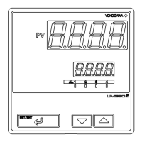
■ OperationDisplaySwitchingDiagram
8 8
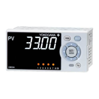
PV Display
SELECT Displays (1 to 5)
PresstheDISPkeytoshowSELECTDisplay-1to-5conditionally.
FortheregistrationoftheSELECTDisplays,seeUser’sManual.
Operation
Guide
UM33A
Digital Indicator with Alarms
Operation Guide
This operation guide describes key entries for operating the UM33A.
For operations using external contact inputs, see “DI” of “6. Terminal Wiring Diagrams”
in “Installation and Wiring.”
If you cannot remember how to carry out an operation during setting, press the
DISP key once. This brings you to the display (Operation Display) that
appears at power-on.
The scrolling guide is displayed on PV display in the Parameter Setting Display.
This guide can be turned on/off with the Fn key.
Operations
2. Setting Alarm Setpoint
Thefollowingoperatingprocedureshowsanexampleofsettingthealarm-1setpoint
to180.0.
Beforesettingthealarmsetpoint,checkthealarmtype.
To change the alarmtype,see “3.SettingAlarmType”in“Initial settings”ofthis
manual.
1.
2.
3.
4.
5.
6.
8
8
AL menu is displayed.
Display the parameter that need to be changed.
Blinks during the change.
Show the Operation Display.
Hold down the PARA key for 3 seconds.
Press the SET/ENTER key.
Press the SET/ENTER key.
Press the SET/ENTER key.
The parameter A1 is displayed.
A1 to A8 represent the alarm-1 to -8
setpoints.
Each parameter can be changed in the
Parameter Setting Displays of alarms
using Up/Down arrow keys .
Change the setpoint using the Up/Down arrow keys to
increase and decrease the value and the Left/Right
arrow keys to move between digits.
The setpoint has been registered.
After the setup is completed, press
the DISP key once to return to the
Operation Display.
3. Troubleshooting
■TroubleshootingFlow
IftheOperationDisplaydoesnotappearafterturningontheindicator’spower,check
theproceduresinthefollowingowchart.
Ifaproblemappearstobecomplicated,contactoursalesrepresentatives.
■RemediesifPowerFailureOccursduringOperations
• Instantaneous power failure within 20 ms.
Apowerfailureisnotdetected.Normaloperationcontinues.
• Power failure for less than about 5 seconds, or for about 5 seconds or more.
Affectsthe"settings"and"operationstatus."
Fordetails,seeUser'sManual.
NOTE
Write down the settings
of parameters for a repair
request.
Is the indicator
defective?
Contact us for repair.
Problem solved.
No communication
capability
Completely
inactive?
Yes
Yes
Yes
No
No
No
Key
operation
failure?
Yes
No
Yes
Check wiring of the
power terminals.
Check the key lock
setting.
Display
failure?
*
Yes
No
Turn off power, and
then turn it on again.
I/O signal
failure?
Yes
No
Check the
supply voltage.
Check the
specifications and polarity
of connected devices .
Check the communication-
related parameters.
Check the specifications
of communication
devices.
Check the
communication wiring.
Communication
failure?
No
With
communi-
cation?
Yes
Yes
Normal?
Is the
key locked?
Check the specifications
of the indicator.
Yes
No
Correct?
Correct the error(s).
Cancel the setting.
Check the I/O specifications
of the indicator.
* The LCD (a liquid crystal display) is used for a
display portion of this product.
The LCD has a characteristic that the display action
becomes late at the low temperature.
Additionally, the luminance and contrast degradation
are caused due to aged deterioration.
However, the function is not affected.
n
Errors at Power On
Theerrorsshownbelowmayoccurinthefaultdiagnosiswhenthepoweristurnedon.(FordetailsofSetpointdisplayandinput/outputactionwheneacherroroccurs,seeUser’sManual.)
PV display
(Operation
Display)
Setpoint display
(Operation Display)
Status indicator
(Operation Display)
Parameter that displays error
details
Error description Cause and diagnosis Remedy
Indication off Indication off
— — FaultyMCURAM/MCUROM MCURAM/MCUROMarefailed.
Faulty.
Contactusforrepair.
ERR
SYS-----
—
— System data error System data is corrupted.
Faulty.
Contactusforrepair.
PAR0004
(foruserdefaultvalueerroronly)
Setupparameter(PA.ER)
User(parameter)defaultvalue
error
Userparameteriscorrupted.
Initializedtofactorydefaultvalue.
Checkandreconguretheinitialized
settingparameters.Errorindicationis
erased when the power is turned on
again.
PAR0010
(forsetupparametererroronly)
Setup parameter error
Setup parameter data is corrupted.
Initializedtouserdefaultvalue.
PAR0020
(foroperationparametererroronly)
Operationparametererror
Operationparameterdataiscorrupted.
Initializedtouserdefaultvalue.
SLOT0001
Setupparameter(OP.ER)
Nonrespondinghardwareof
extendedfunction(E1-terminal
area)
Inconsistence of system data and hardware of
extendedfunction.
Nonrespondingcommunicationbetweenhardware
ofextendedfunction(E1-terminalarea).
Faulty.
Contactusforrepair.
Normal
indication
Normalindication
Rightmostdecimalpoint
onPVdisplayblinks.
Setupparameter(PA.ER)
Calibrationvalueerror
Initializedtocalibrateddefaultvaluebecause
ofcorruptedfactorydefaultvalue.
Faulty.
Contactusforrepair.
Rightmostdecimalpoint
onSymboldisplayblinks.
FaultyFRAM
Datawriting(storing)toFRAMisimpossible.
n
Errors during Operation
Theerrorsshownbelowmayoccurduringoperation.(Forinput/outputactionwheneacherroroccurs,seeUser’sManual.)
PV display
(Operation
Display)
Setpoint display
(Operation Display)
Status indicator
(Operation Display)
Parameter that displays
error details
Error description Cause and diagnosis Remedy
AD.ERR
Normalindication — Setupparameter(AD1.E)
AnaloginputterminalADCerror
•PVinput
AnaloginputterminalADvalueerror
Faulty.
Contactusforrepair.
RJC.E
(DisplaysRJC.
EandPV
alternately.)
Normalindication — Setupparameter(AD1.E)
UniversalinputterminalRJCerror
•PVinput
UniversalinputterminalRJCerror
Faulty.
Contactusforrepair.
SettheparameterRJCtoOFFtoerase
error indication.
B.OUT
Normalindication —
Setupparameter(AD1.E)
Analoginputterminalburnouterror
•PVinput
Analoginputterminalsensorburnout
Checkwiringandsensor.
Errorindicationiserasedinnormal
operation.
Setupparameter(PV1.E) PVinputburnouterror BurnoutofanaloginputconnectedtoPV
Checkwiringandsensorofconnected
analoginputterminals.
Errorindicationiserasedinnormal
operation.
OVER
-OVER
Normalindication — Setupparameter(PV1.E)
PVinputover-scale
PVinputunder-scale
(PVvaluesoutof-5to105%)
PVinputisoutof-5to105%.Alsooccurs
whenthedataoutofrangewhichisthe
ladder calculation result is input.
Checkanaloginputvalueorladder
program.
Normal
indication
0.00000000
(Decimalpointontheleftof
theSymboldisplayblinks)
— Setupparameter(OP.ER)
Communicationerror
(RS-485communication)
Framingparityerror
Bufferoverow
Inter-charactertime-out
Checksumerror(PClinkcommunicationwith
checksum)
CRCcheckerror(Modbus/RTU)
LRCcheckerror(Modbus/ASCII)
Checkthecommunicationparameters.
Recoveryatnormalreceipt.
Holddownanykeytostopblinking.
Normal
indication
Normalindication
Rightmostdecimalpointon
Symboldisplayblinks.
Setupparameter(PA.ER) FaultyFRAM
Writing(storing)datatoFRAMisimpossible.
Faulty.Contactusforrepair.
Undened Undened — —
FaultyMCU/DCU
(ROM/RAMerror,corrupted)
MCU/DCUiscorrupted. Faulty.Contactusforrepair.
 Loading...