IM 05P03D21-11EN page 7/8
Operation Parameters
HolddownthePARAkeyfor3secondstomovefromtheOperationDisplaytotheOp-
erationParameterSettingDisplay.PresstheDISPkeyoncetoreturntotheOperation
Display.
Menu
Hold down PARA key
for 3 sec.
DISP key
SET/ENTER key
PARA key
key key key
key
key
Operation Dsipaly
Parameter
Parameter
Parameter
Parameter
Parameter
Parameter
END
Menu
END
Menu END
END
Menu Display and
Parameter Setting
Display are changed
in a circular pattern.
Move to the Setup Parameter Setting Display:
Hold down the PARA key and the Left arrow key simultaneously for 3 sec.
Operation for Setting
· Toselecttheparametersettingdisplayedastheinitialvalue,presstheDownarrow
keytomovetothenextparameter.
· Tochangeandsettheparametersetting,presstheSET/ENTERkeytostarttheset
-
pointblinking.Theblinkingstateallowsyoutomakechanges(settingmode).Usethe
Up/Down/Left/Rightarrowkeystochangethesetpoint.PresstheSET/ENTERkeyto
registerthesetting.
Notethattherearesomeparameterswhicharenotdisplayeddependingonthemodelandsuffix
codes.
n
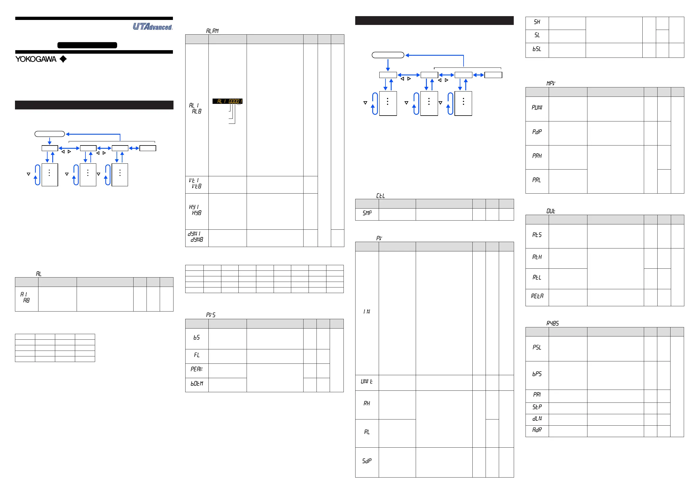
Alarm Setpoint Setting Parameter
Menusymbol: (AL)
Parameter
symbol
Name of Parameter Setting Range
Initial
value
User
setting
Display
level
to
(A1toA8)
Alarm-1to-8setpoint
SetadisplayvalueofsetpointofPV
alarmorvelocityalarm.
-19999to30000(Setavaluewithin
theinputrange.)
Decimalpointpositiondependson
the input type
0
Table
below
EASY
Forthealarmsetpoint parameter,alarm-1 to-8are displayedforthe factory default.
Thenumberofalarms canbechangedusingthesetupparameterALNO. (numberof
alarms).Tochangethenumberofalarms,seeUser'sManual.
Usethefollowingtabletorecordalarmsetpoints.
Parameter Setpoint Parameter Setpoint
A1 A5
A2 A6
A3 A7
A4 A8
n
Alarm Function Setting Parameter
Menusymbol: (ALRM)
Parameter
symbol
Name of Parameter Setting Range
Initial
value
User
setting
Display
level
to
(AL1toAL8)
Alarm-1to8type
Example:Alarm-1
Stand-by
action
Latch action
Energized/
De-energize
Alarm
type
Seta5-digitvalueinthefollowing
order.
[Alarmtype:2digits(seebelow)]+
[Without(0)orWith(1)Stand-byac
-
tion]+[Energized(0)orDe-energized
(1)]+[Latchaction(0/1/2/3/4)]
Forlatchaction,seeUser'sManual.
AL1,
AL3,
AL5,
AL7:
PVhigh
limit(01)
Without
Stand-
by
action
(0)
Ener-
gized(0)
Latch
action
(0)
AL2,
AL4,
AL6,
AL8:
PVlow
limit(02)
Without
Stand-
by
action
(0)
Ener-
gized
(0)
Latch
action
(0)
Table
below
EASY
Alarmtype:2digits
00:Disable
01:PVhighlimit
02:PVlowlimit
29:PVvelocity
30:Faultdiagnosis
31:FAIL
to
(VT1toVT8)
PVvelocityalarmtime
setpoint1to8
0.01to99.59(minute.second)
1.00
to
(HY1toHY8)
Alarm-1to-8hysteresis
Setadisplayvalueofsetpointof
hysteresis.
-19999to30000(Setavaluewithin
theinputrange.)
Decimalpointpositiondependson
the input type.
Whenthedecimalpointpositionfor
theinputtypeissetto"1",theinitial
valueofthehysteresisis"1.0".
10
to
(DYN1toDYN8)
Alarm-1to-8On-delay
timer
AnalarmoutputisONwhenthedelay
timerexpiresafterthealarmsetpoint
is reached.
0.00to99.59(minute.second)
0.00 STD
Forthealarmfunctionsettingparameter,8alarmsaredisplayedforthefactorydefault.
Thenumberofalarms canbe changed by thesetup parameterALNO. (number of
alarms).Tochangethenumberofalarms,seeUser'sManual.
Parameter n=1 n=2 n=3 n=4 n=5 n=6 n=7 n=8
ALn
VTn
HYn
DYNn
n:alarmnumber
n
PV-related Setting Parameter
Menusymbol: (PVS)
Parameter
symbol
Name of Parameter Setting Range
Initial
value
User
setting
Display
level
(BS)
PVinputbias
-100.0to100.0%ofPVinputrange
span(EUS)
0.0%
ofPV
input
range
span
EASY
(FL)
PVinputlter OFF,1to120s
OFF
(PEAK)
PVpeakvalue
Displayonly
(-5.0to105.0%ofPVinputrange
(EU))
None
(BOTM)
PVbottomvalue
None
Setup Parameters
Holddown the PARAkey andLeftarrowkeysimultaneously for 3secondstomove
fromthe Operation DisplayorOperationParameterSettingDisplay totheSetup Pa
-
rameterSettingDisplay.
PresstheDISPkeyoncetoreturntotheOperationDisplay.
Menu
DISP key
SET/ENTER key
PARA key
key key key
key
key
Operation Dsipaly
Parameter
Parameter
Parameter
Parameter
Parameter
Parameter
END
Menu
END
Menu END
END
Menu Display and
Parameter Setting
Display are changed
in a circular pattern.
Move to the Operation Parameter Setting Display:
Hold down the PARA key for 3 sec.
Hold down PARA key and
Left arrow key simultaneously for 3 sec.
Operation for Setting
· Toselecttheparametersettingdisplayedastheinitialvalue,presstheDownarrow
keytomovetothenextparameter.
· Tochangeandsettheparametersetting,presstheSET/ENTERkeytostarttheset
-
pointblinking.Theblinkingstateallowsyoutomakechanges(settingmode).Usethe
Up/Down/Left/Rightarrowkeystochangethesetpoint.PresstheSET/ENTERkeyto
registerthesetting.
NotethattherearesomeparameterswhicharenotdisplayeddependingontheModelandSuffixcodes.
n
Function Setting Parameter
Menusymbol: (CTL)
Parameter
symbol
Name of Parameter Setting Range
Initial
value
User
setting
Display
level
(SMP)
Inputsamplingperiod 50:50ms,100:100ms,200:200ms
50 STD
n
PV Input Setting Parameter
Menusymbol: (PV)
Parameter
symbol
Name of Parameter Setting Range
Initial
value
User
setting
Display
level
(IN)
PVinputtype
OFF:Disable
K1:-270.0to1370.0
0
C/-450.0to2500.0
0
F
K2:-270.0to1000.0
0
C/-450.0to2300.0
0
F
K3:-200.0to500.0
0
C/-200.0to1000.0
0
F
J:-200.0to1200.0
0
C/-300.0to2300.0
0
F
T1:-270.0to400.0
0
C/-450.0to750.0
0
F
T2:0.0to400.0
0
C/-200.0to750.0
0
F
B:0.0to1800.0
0
C/32to3300
0
F
S:0.0to1700.0
0
C/32to3100
0
F
R:0.0to1700.0
0
C/32to3100
0
F
N:-200.0to1300.0
0
C/-300.0to2400.0
0
F
E:-270.0to1000.0
0
C/-450.0to1800.0
0
F
L:-200.0to900.0
0
C/-300.0to1600.0
0
F
U1:-200.0to400.0
0
C/-300.0to750.0
0
F
U2:0.0to400.0
0
C/-200.0to1000.0
0
F
W:0.0to2300.0
0
C/32to4200
0
F
PL2:0.0to1390.0
0
C/32.0to2500.0
0
F
P2040:0.0to1900.0
0
C/32to3400
0
F
WRE:0.0to2000.0
0
C/32to3600
0
F
JPT1:-200.0to500.0
0
C/-300.0to1000.0
0
F
JPT2:-150.0to150.0
0
C/-200.0to300.0
0
F
PT1:-200.0to850.0
0
C/-300.0to1560.0
0
F
PT2:-200.0to500.0
0
C/-300.0to1000.0
0
F
PT3:-150.00to150.00
0
C/-200.0to300.0
0
F
0.4-2V:0.400to2.000V
1-5V:1.000to5.000V
4-20:4.00to20.00mA
0-2V:0.000to2.000V
0-10V:0.00to10.00V
0-20:0.00to20.00mA
-1020:-10.00to20.00mV
0-100:0.0to100.0mV
OFF EASY
(UNIT)
PVinputunit
-:Nounit,C:DegreeCelsius
-:Nounit,--:Nounit,---:Nounit,
F:DegreeFahrenheit
C EASY
(RH)
MaximumvalueofPV
inputrange
Dependsontheinputtype.
-Fortemperatureinput-
Setthetemperaturerangethatis
actuallydisplayed.(RL<RH)
-Forvoltage/currentinput-
Settherangeofavoltage/current
signalthatisapplied.
Thescaleacrosswhichthevoltage
/currentsignalisactuallydisplayed
shouldbesetusingthemaximum
valueofinputscale(SH)and
minimumvalueofinputscale(SL).
(Inputisalways0%whenRL=RH.)
Depends
on the
input type
EASY
(RL)
MinimumvalueofPV
inputrange
(SDP)
PVinputscaledecimal
point position
0:Nodecimalplace
1:Onedecimalplace
2: Two decimal places
3: Three decimal places
4: Four decimal places
Depends
on the
input type
EASY
(SH)
MaximumvalueofPV
input scale
-19999to30000,(SL<SH),
|SH-SL|≤30000
Depends
on the
input type
EASY
(SL)
MinimumvalueofPV
input scale
(BSL)
PVinputburnoutaction
OFF:Disable
UP:Upscale
DOWN:Downscale
Depends
on the
input type
STD
W:W-5%Re/W-26%Re(HoskinsMfg.Co.).ASTME988
WRE:W97Re3-W75Re25
n
Input Range Setting Parameter
Menusymbol: (MPV)
Parameter
symbol
Name of Parameter Setting Range
Initial
value
User
setting
Display
level
(P.UNI)
DisplayPVinputunit
-:Nounit
C:DegreeCelsius
-:Nounit
--:Nounit
---:Nounit
F:DegreeFahrenheit
Same
asPV
input
unit
STD
(P.DP)
DisplayPVinputdecimal
point position
0:Nodecimalplace
1:Onedecimalplace
2: Two decimal places
3: Three decimal places
4: Four decimal places
1
(P.RH)
Maximumvalueof
displayPVinputrange
-19999to30000,(P.RL<P.RH),
|P.RH-P.RL|≤30000
Depends
on the
input type
(P.RL)
Minimumvalueofdisplay
PVinputrange
n
Output Setting Parameter
Menusymbol: (OUT)
Parameter
symbol
Name of Parameter Setting Range
Initial
value
User
setting
Display
level
(RTS)
Retransmissionoutput
typeofRET
OFF:Disable
PV1:PV
LPS:15VDClooppowersupply
PV1 EASY
(RTH)
Maximumvalueof
retransmission output
scaleofRET
WhenRTS=PV1
RTL+1digitto30000
-19999toRTH-1digit
Decimalpointposition:When
RTS=PV1,decimalpointposition
issameasthatofPVinput.
WhenRTS=PV,decimalpointposition
issameasthatofPVinputscale.
100%
ofPV
input
range
STD
(RTL)
Minimumvalueof
retransmission output
scaleofRET
0%
ofPV
input
range
(RET.A)
RETcurrentoutput
range
4-20:4to20mA
0-20:0to20mA
20-4:20to4mA
20-0:20to0mA
4-20
n
RS-485 Communication Setting Parameter (E1-terminal Area)
Menusymbol: (R485)
Parameter
symbol
Name of Parameter Setting Range
Initial
value
User
setting
Display
level
(PSL)
Protocol selection
PCL:PClinkcommunication
PCLSM:PClinkcommunication(with
checksum)
LADR:Laddercommunication
MBASC:Modbus(ASCII)
MBRTU:Modbus(RTU)
MBRTU
EASY
(BPS)
Baud rate
600:600bps
1200:1200bps
2400:2400bps
4800:4800bps
9600:9600bps
19200:19.2kbps
38400:38.4kbps
19200
(PRI)
Parity
NONE:None
EVEN:Even
ODD:Odd
EVEN
(STP)
Stopbit 1:1bit,2:2bits
1
(DLN)
Datalength 7:7bits,8:8bits
8
(ADR)
Address 1to99 1
Operation
Guide
UM33A
Digital Indicator with Alarms
Operation Guide
This operation guide describes the functions of parameters briefly. The parameter
symbols listed are in the order shown on the display in each group of menu symbols.
In addition, each parameter table has a “User Setting” column, where you can record
your setpoints when setting them in the indicator. The scrolling guide is displayed on
PV display in the Parameter Setting Display. This guide can be turned on/off with
the Fn key.
Yokogawa Electric Corporation
Parameters
 Loading...