IM 05P03D21-11EN page 5/8
Contents
1. NamesandFunctionsofDisplayParts
2. QuickSettingFunction(SettingofInputandOutput)
3. SettingAlarmType
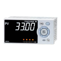
1. Names and Functions of Display Parts
(1)
(2)
(3)
(4)
(5)
(11)
(8)
(6)
(7)
(13)
(12)
(10)
(9)
No.ingure Name Description
(1)
PVdisplay
(whiteorred)
DisplaysPV.
Displaysanerrorcodeifanerroroccurs.
DisplaysthescrollingguideintheMenuDisplayandParameter
SettingDisplaywhentheguidedisplayON/OFFissettoON.
(2) Groupdisplay(green)
Displaysagroupnumber.
(3)
Symboldisplay(orange)
Displaysaparametersymbol.
(4) Datadisplay(orange) Displaysaparametersetpointandmenusymbol.
(5)
Eventindicator
(orange)
Litwhenthealarms1to8occur.
Eventdisplaysotherthanalarmscanbesetbytheparameter.
(6)
Keynavigationindica
-
tor(green)
LitorblinkswhentheUp/DownorLeft/Rightarrowkeyoperation
ispossible.
(7)
Parameterdisplaylevel
indicator(green)
Displaysthesettingconditionsoftheparameterdisplaylevelfunc
-
tion.
Parameter display level EASY PRO
Easysettingmode
Lit Unlit
Standardsettingmode
Unlit Unlit
Professionalsettingmode
Unlit Lit
(8) Securityindicator(red) Litifapasswordisset.Thesetupparametersettingsarelocked.
No.ingure Name Description
(9) DISPkey
UsedtoswitchtheOperationDisplays.
PressthekeyintheOperationDisplaytoswitchtheprovided
SELECTDisplays.
PressthekeyintheMenuDisplayorParameterSettingDisplay
toreturntotheOperationDisplay.
(10) PARAkey
Holddownthekeyfor3secondstomovetotheOperation
ParameterSettingDisplay.
HolddownthekeyandtheLeftarrowkeysimultaneouslyfor3
secondstomovetotheSetupParameterSettingDisplay.
PressthekeyintheParameterSettingDisplaytoreturntothe
MenuDisplay.Pressthekeyoncetocanceltheparameterset
-
ting(setpointisblinking).
(11)
SET/ENTERkey
Up/Down/Left/Right
arrow keys
SET/ENTERkey
PressthekeyintheMenuDisplaytomovetotheParameter
SettingDisplayoftheMenu.PressthekeyintheParameter
SettingDisplaytotransfertotheparametersettingmode
(setpointisblinking),andtheparametercanbechanged.
Pressthekeyduringparametersettingmodetoregisterthe
setpoint.
Up/Down/Left/Rightarrowkeys
PresstheLeft/RightarrowkeysintheMenuDisplaytoswitch
theDisplays.
PresstheUp/DownarrowkeysintheParameter
SettingDisplaytoswitchtheDisplays.
PresstheUp/Downarrowkeysduringparametersettingmode
(setpointisblinking)tochangeasetpoint.
PresstheLeft/Rightarrowkeysduringparametersettingmode
(setpointisblinking)tomovebetweendigitsaccordingtotheparameter.
(12) Light-loaderinterface
Itisthecommunicationinterfacefortheadaptercableusedwhen
settingandstoringparametersfromaPC.TheLL50AParameter
SettingSoftware(soldseparately)isrequired.
(13) Userfunctionkeys
Fnkey.Theusercanassignafunctiontothekey.Thefunctionis
setbytheparameter.
Note: Thecommunicationconnector(maintenanceport)forLL50AParameterSettingSoftwareis
on the side of the unit.
2.
Quick Setting Function (Setting of Input and Output)
TheQuicksettingfunctionisafunctiontoeasilysetthebasicfunctionoftheindicator.
TurnontheindicatortostarttheQuicksettingfunction.
Thisfunctionallowsyoutoeasilysettheinput,andquicklystartthealarmaction.
Theitems(parameters)tobesetbyQuicksettingfunctionareasfollows.
(1)Inputfunction(PVinputtype,range,scale(atvoltageinput),etc.)
Afterturningontheindicator,rstdecidewhetherornottousetheQuicksettingfunction.
Operation in Initial Display
· PresstheSET/ENTERkeywhileYESisdisplayedtostarttheQuicksettingfunction.
· IfyouchangeYES to NOandpresstheSET/ENTERkey,OperationDisplaywill
appearwithoutstartingtheQuicksettingfunction.
Operation for Setting
· Toselecttheparametersettingdisplayedastheinitialvalue,presstheDownarrow
keytomovetothenextparameter.
· Tochangeandsettheparametersetting, presstheSET/ENTERkeytostartthe
setpoint blinking.Theblinking stateallowsyou tomakechanges (settingmode).
UsetheUp/Down/Left/Rightarrowkeystochangethesetpoint.PresstheSET/EN
-
TERkeytoregisterthesetting.
■ MakingSettingsUsingQuickSettingFunction
Example: Setting to thermocouple type K (range of 0.0 to 500.0
0
C).
Forthedetailedprocedureandswitchingofdisplays,see"FlowofQuickSetting
Function"below.Fortheparameterstoset,seethenextpage.
(1)PresstheSET/ENTERkeywhileYESforQSM(Quicksettingmode)isdisplayed.
(2)SetthePVinputtypeparameter(IN)toK1(-270.0to1370.0
0
C).
(3)SetthePVinputunitparameter(UNIT)toC(DegreeCelsius).
(4)SetthemaximumvalueofPVinputrangeparameter(RH)to500.0.
(5)SettheminimumvalueofPVinputrangeparameter(RL)to0.0.
(6)Finally,EXITisdisplayed.ChangeNOtoYESandpresstheSET/ENTERkeyto
completethesetup.OperationDisplayappears.
■ FlowofQuickSettingFunction
InQuicksettingmode,theparameterguideappearsonPVdisplay.
Thisguidecanbeturnedon/offwiththeFnkey.
8
1.
2.
3.
4.
5.
6.
8.
9.
10.
11.
7.
8
8
8
8
Power-on
Quick setting starts
The PV input type
parameter (IN) is
displayed.
Initial value: OFF
OFF blinks.
Blinking allows you to
change the setting.
K1 is displayed.
K1 has been registered.
The last digit of the upper limit value blinks.
The parameter RH (maximum value of PV input
range) has been changed to 500.0.
The setpoint for the parameter RH has been
registered.
The PV input unit parameter (UNIT) is displayed.
Initial value: C (Degree Celsius)
Select NO with
the Down arrow
key and press
the SET/ENTER
key.
Press the SET/ENTER key while YES
is displayed to start the Quick setting.
[YES]
[NO]
Press the SET/ENTER key.
Press the SET/ENTER key.
Press the SET/ENTER key.
Press the SET/ENTER key.
Press the Up arrow key.
Select NO to return to
the Operation Display.
Press the Down arrow key.
Press the Down arrow key.
Press the Down arrow key.
The upper limit value of the setting range is displayed
for the parameter RH (maximum value of PV input
range).
Change the setpoint using the Up/Down
arrow keys to increase and decrease the
value and the Left/Right arrow keys to move
between digits.
Finally, EXIT is displayed.
Press the SET/ENTER key to swtich to the
setting mode.
Change NO to YES and press the
SET/ENTER key to complete the setup of
the basic function.
Operation Display appears.
The Quick setting function continues in the
NO state.
Operation Display
Displays the
measured input
value (PV).
Follow the same procedure to set RL.
Operation
Guide
Initial Settings
UM33A
Digital Indicator with Alarms
Operation Guide
This operation guide describes basic settings and operations of the UM33A.
For details of each function, see the electronic manual.
The scrolling guide is displayed on PV display in the Parameter Setting Display.
This guide can be turned on/off with the Fn key.
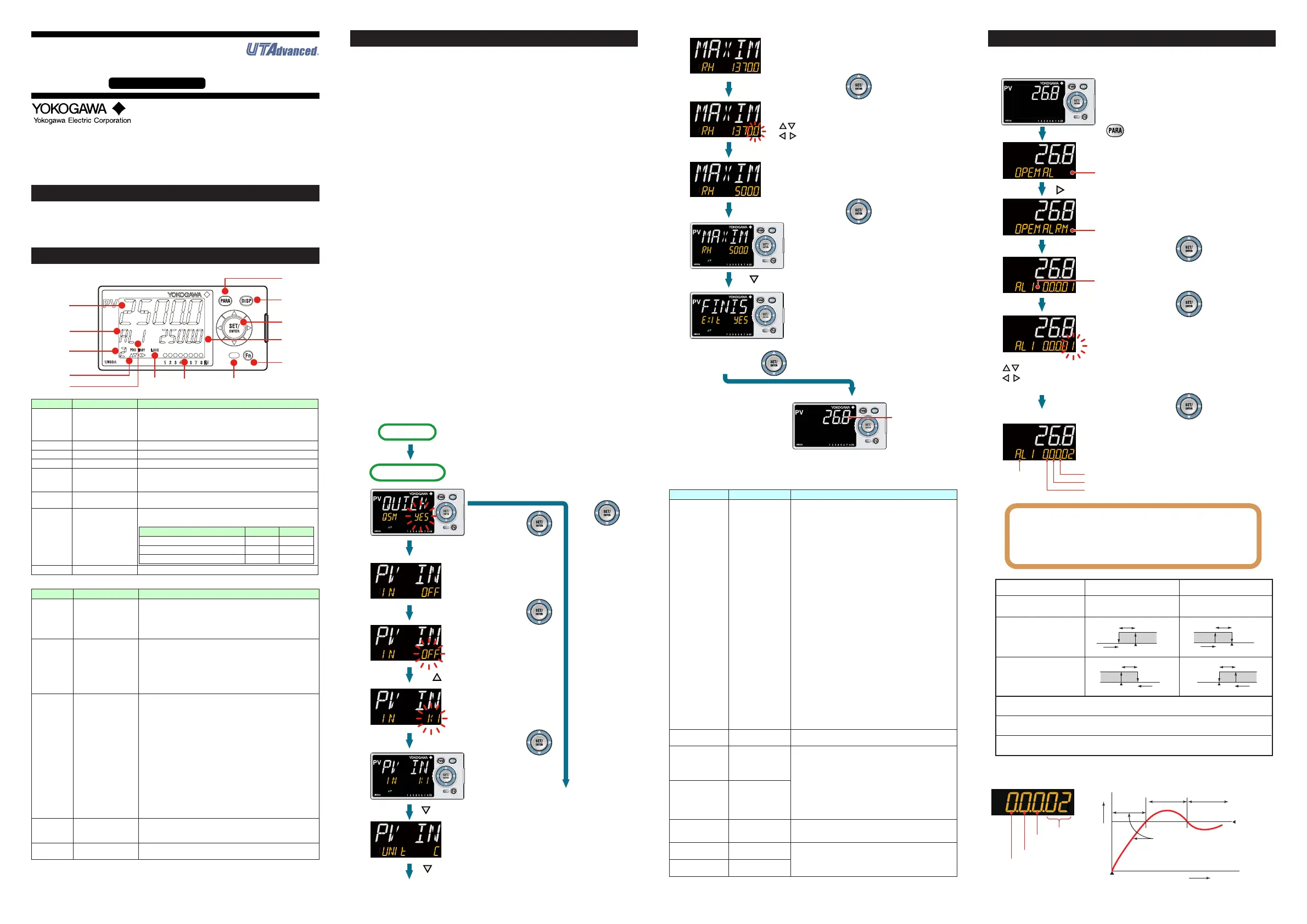
3. Setting Alarm Type
Thefollowingoperatingprocedureshowsanexampleofchangingthealarm-1type
(factorydefault:PVhighlimitalarm)toPVlowlimitalarm.
1.
2.
3.
4.
5.
6.
8
AL menu is displayed.
ALRM menu is displayed.
Show the Operation Display.
Hold down the key for 3 seconds.
Press the Right arrow key.
Press the SET/ENTER key.
Press the SET/ENTER key.
Press the SET/ENTER key.
The parameter AL1 (alarm-1 type) is
displayed.
The last digit of the setpoint blinks.
Change the setpoint using the Up/Down arrow keys
to increase and decrease the value and the
Left/Right arrow keys to move between digits.
The alarm-1 type setpoint 02 (PV low limit) is
registered.
After the setup is completed, press the DISP key
once to return to the Operation Display.
● To change the alarm type, change the last 2 digits of the 5-digit
value.
● Stand-by action and excitation are turned on or off by selecting 1 or
0. (See “ Setting Display of Alarm Type.”)
● For the latch action, see User ’ s Manual.
Symbol
Stand-by action
Energized/De-energized
Latch action
- -
No alarm (00)
Alarm Action (De-energized)
PV high limit (01)
PV low limit (02)
PV velocity (29)
Fault diagnosis alarm (30)
FAIL (31)
Alarm Type (Alarm Setpoint) Alarm Action (Energized)
Hysteresis
Alarm setpoint
PV
Closed
(lit)
Open
(unlit)
Alarm setpoint
Hysteresis
PV
Closed
(lit)
Open
(unlit)
Hysteresis
Alarm setpoint
PV
Open
(lit)
Closed
(unlit)
Alarm setpoint
Hysteresis
PV
Open
(lit)
Closed
(unlit)
Burnout of PV input, ADC failure, RJC error.
For the factory default, the contact output is turned ON in normal operation,
OFF at the time of FAIL. Alarm output: OFF
Note 1: “Open/closed” shows status of relay contact, and “lit/unlit” shows status of EV (event) lamp.
Setting Display of Alarm Type Stand-by Action
Energized (0) / De-energized (1)
Alarm type
Without (0) or With (1)
Stand-by action
Latch action (0/1/2/3/4)
See User’s Manual.
PV low limit
alarm setpoint
Treated
as normal
ºC
Power-on
Time
The alarm output does not turn on
in this region even if the PV valule
is below PV low limit alarm setpoint.
Normal Abnormal
The alarm output
turns on.
8
1.
2.
3.
4.
5.
6.
8.
9.
10.
11.
7.
8
8
8
8
Power-on
Quick setting starts
The PV input type
parameter (IN) is
displayed.
Initial value: OFF
OFF blinks.
Blinking allows you to
change the setting.
K1 is displayed.
K1 has been registered.
The last digit of the upper limit value blinks.
The parameter RH (maximum value of PV input
range) has been changed to 500.0.
The setpoint for the parameter RH has been
registered.
The PV input unit parameter (UNIT) is displayed.
Initial value: C (Degree Celsius)
Select NO with
the Down arrow
key and press
the SET/ENTER
key.
Press the SET/ENTER key while YES
is displayed to start the Quick setting.
[YES]
[NO]
Press the SET/ENTER key.
Press the SET/ENTER key.
Press the SET/ENTER key.
Press the SET/ENTER key.
Press the Up arrow key.
Select NO to return to
the Operation Display.
Press the Down arrow key.
Press the Down arrow key.
Press the Down arrow key.
The upper limit value of the setting range is displayed
for the parameter RH (maximum value of PV input
range).
Change the setpoint using the Up/Down
arrow keys to increase and decrease the
value and the Left/Right arrow keys to move
between digits.
Finally, EXIT is displayed.
Press the SET/ENTER key to swtich to the
setting mode.
Change NO to YES and press the
SET/ENTER key to complete the setup of
the basic function.
Operation Display appears.
The Quick setting function continues in the
NO state.
Operation Display
Displays the
measured input
value (PV).
Follow the same procedure to set RL.
■ Parameterstobeset
Input Function
Parameter Symbol Name of Parameter Setting Range
IN PVinputtype
OFF:Disable
K1:-270.0to1370.0
0
C/-450.0to2500.0
0
F
K2:-270.0to1000.0
0
C/-450.0to2300.0
0
F
K3:-200.0to500.0
0
C/-200.0to1000.0
0
F
J:-200.0to1200.0
0
C/-300.0to2300.0
0
F
T1:-270.0to400.0
0
C/-450.0to750.0
0
F
T2:0.0to400.0
0
C/-200.0to750.0
0
F
B:0.0to1800.0
0
C/32to3300
0
F
S:0.0to1700.0
0
C/32to3100
0
F
R:0.0to1700.0
0
C/32to3100
0
F
N:-200.0to1300.0
0
C/-300.0to2400.0
0
F
E:-270.0to1000.0
0
C/-450.0to1800.0
0
F
L:-200.0to900.0
0
C/-300.0to1600.0
0
F
U1:-200.0to400.0
0
C/-300.0to750.0
0
F
U2:0.0to400.0
0
C/-200.0to1000.0
0
F
W:0.0to2300.0
0
C/32to4200
0
F
PL2:0.0to1390.0
0
C/32.0to2500.0
0
F
P2040:0.0to1900.0
0
C/32to3400
0
F
WRE:0.0to2000.0
0
C/32to3600
0
F
JPT1:-200.0to500.0
0
C/-300.0to1000.0
0
F
JPT2:-150.00to150.00
0
C/-200.0to300.0
0
F
PT1:-200.0to850.0
0
C/-300.0to1560.0
0
F
PT2:-200.0to500.0
0
C/-300.0to1000.0
0
F
PT3:-150.00to150.00
0
C/-200.0to300.0
0
F
0.4-2V:0.400to2.000V
1-5V:1.000to5.000V
4-20:4.00to20.00mA
0-2V:0.000to2.000V
0-10V:0.00to10.00V
0-20:0.00to20.00mA
-1020:-10.00to20.00mV
0-100:0.0to100.0mV
UNIT PVinputunit
-:Nounit,C:DegreeCelsius
-:Nounit,--:Nounit,---:Nounit,F:DegreeFahrenheit
RH
Maximumvalueof
PVinputrange
Dependsontheinputtype.
-Fortemperatureinput-
Setthetemperaturerangethatisactuallydisplayed.
(RL<RH)
-Forvoltage/currentinput-
Settherangeofavoltage/currentsignalthatisapplied.
Thescaleacrosswhichthevoltage/currentsignalis
actuallydisplayedshouldbesetusingthemaximumvalue
ofinputscale(SH)andminimumvalueofinputscale(SL).
(Inputisalways0%whenRL=RH.)
RL
Minimumvalueof
PVinputrange
SDP
PVinputscale
decimal point
position
0:Nodecimalplace
1:Onedecimalplace
2: Two decimal places
3: Three decimal places
4: Four decimal places
SH
Maximumvalueof
PVinputscale
-19999to30000,(SL<SH),|SH-SL|≤30000
SL
Minimumvalueof
PVinputscale
Note1:SDP,SH,andSLaredisplayedonlyforvoltage/currentinput.
Note2:W:W-5%Re/W-26%Re(HoskinsMfg.Co.),ASTME988
 Loading...