<Toc> <1. Installation>
1-9
IM 05D01D02-41E 1st Edition : May 31,2000-00
• On/off determination: For non-voltage contact input, contact resistance of 1 k or less
is determined as “on” and contact resistance of 20 k or more as “off.”
For transistor open collector input, input voltage of 2 V or less is determined as “on”
and leakage current must not exceed 100 A when “off.”
• Minimum status detection hold time: About 1 sec.
Contact Outputs
• Purpose: Alarm output, FAIL output, and others
• Number of outputs: 3
• Relay contact rating: 240 V AC/1 A or 30 V DC/1 A (COM terminal is common.)
Display Specifications
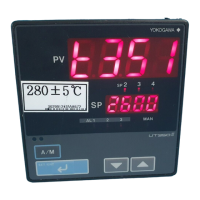
• PV display:
UT350: 4-digit, 7-segment red LED display, character height of 20 mm
UT320: 4-digit, 7-segment red LED display, character height of 12 mm
• Setpoint display: 4-digit, 7-segment red LED display, character height of 9.3 mm (for
both UT350 and UT320)
• Status indicating lamps: LEDs
Safety and EMC Standards
• Safety: Compliant with IEC1010-1: 1990 and EN61010-1: 1992
Approved by CSA1010
CSA1010 installation category (overvoltage category): CATII (IEC1010-1)
Approved by UL508
• EMC standards: This instrument complies with the following EMC standards (the
instrument continues to operate at a measuring accuracy of within 20% of the range
during tests):
- EMI (emission), EN61326-1: 1997+Am1: 1998
- EMS (immunity), EN61326-1: 1997+Am1: 1998
Construction, Installation, and Wiring
• Construction: Only the front panel is dust-proof and drip-proof (protection class IP55)
For side-by-side close installation the controller loses its dust-proof and drip-proof
protection.
• Material: ABS resin and polycarbonate
• Case color: Black
• Weight: About 1 kg or less
• Dimensions:
UT350 96 (W) 96 (H) 100 (depth from panel face) mm
UT320 48 (W) 96 (H) 100 (depth from panel face) mm
• Installation: Panel-mounting type. With top and bottom mounting hardware (1 each)
• Panel cutout dimensions:
UT350 92
0
+0.8
(W) 92
0
+0.8
(H) mm
UT320 45
0
+0.6
(W) 92
0
+0.8
(H) mm
• Installation position: Up to 30 upward facing (not designed for facing downward)
• Wiring: M3.5 screw terminals (for signal wiring and power/ground wiring as well)

 Loading...