Do you have a question about the YOKOGAWA YS1500 and is the answer not in the manual?
Key characteristics and capabilities of the YS1000 series controllers.
Glossary of essential terms used in the manual for process control.
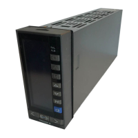
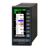
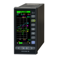
Identifies and describes the components on the front panel of the instrument.
Instructions on how to open and close the front panel of the instrument.
Details the components visible on the internal panel when the front panel is open.
Covers fundamental operations, display switching, and key functions of the instrument.
Explains how to monitor and control the instrument's operations across various displays.
Guides users on setting and displaying control parameters like PID.
Details how to configure controller functions, registers, and settings.
Provides instructions for tuning control functions and parameters for novice users.
Covers essential information and procedures for installing and wiring the instrument.
Procedures to diagnose and resolve issues indicated by ALM and FAIL lamps.
Details diagnostic results for current output errors and possible circuit issues.
Describes backup operations when the instrument experiences failure.
Outlines procedures for instrument recovery after a power failure.
Explains the structure and notation used in the parameter tables.
| Model | YS1500 |
|---|---|
| Type | Single-loop Controller |
| Display | LCD with backlight |
| Control Mode | PID Control |
| Input Types | Thermocouple, RTD, DC Voltage, DC Current |
| Output Types | Relay, Voltage, Current |
| Communication | Ethernet (optional) |
| Power Supply | 100 to 240 V AC, 50/60 Hz or 24 V DC |
| Dimensions | 96 x 96 mm |
