Do you have a question about the YOKOGAWA YS1000 Series and is the answer not in the manual?
| Type | Single-loop controller |
|---|---|
| Input Types | Thermocouple, RTD, Voltage, Current |
| Output Types | Voltage, Current |
| Control Algorithm | PID |
| Communication Protocols | Modbus |
| Communication Interface | RS-485 |
| Power Supply | 100 to 240 V AC, 24 V DC |
Details critical safety guidelines and warnings for instrument operation and installation.
Provides handling precautions, safety symbols, and WEEE directive information.
Lists included accessories and information on accessing electronic user manuals.
Details the instrument's features and defines key operational terms like PV, SV, MV, and PID control.
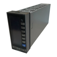
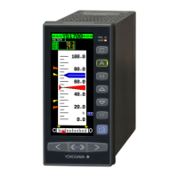
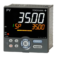
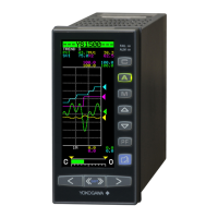
Details all parts and indicators on the instrument's front panel, including display and keys.
Illustrates and names internal components visible when the front panel is swung up.
Visualizes the sequence for unpacking, installation, power-on, programming, and tuning.
Describes the three display groups (Operation, Tuning, Engineering) and how to switch between them.
Details the function of software keys displayed on the LCD, mapped to physical operation keys.
Illustrates display switching paths for the YS1500 in single-loop mode.
Shows display switching paths for cascade and selector modes.
Illustrates display switching paths for the YS1700 in programmable mode.
Details operations on the LOOP Display, including mode switching, SV/MV setting, and PF key functions.
Explains how to monitor and operate the METER Display, similar to analog meters.
Describes keystrokes for various settings and operations on the LOOP Display.
Details operations available on the METER Display for monitoring PV, SV, and MV.
Explains how to use TREND displays for monitoring process variables over time.
Covers operations for TREND 1, 2, and 3 displays, including mode switching and MV/PF key operations.
Details how to view and acknowledge alarms and events using the ALARM Display.
Explains the DUAL Display for monitoring two loops simultaneously and its operations.
Details the key presses required to change between operation modes like Automatic, Manual, and Cascade.
Explains how to configure digital inputs for switching operation modes in cascade and selector modes.
Provides examples and procedures for setting PID parameters like proportional band and integral time.
Details how to set alarm setpoints for PV, deviation, and velocity, including hysteresis.
Explains how to change the controller mode (e.g., SINGLE, CASCADE) and its implications.
Guides on configuring control types (PID, PD) and operation formulas (I-PD, PI-D).
Details how to set the scale range and decimal point position for process variables.
Explains how to set the tag number and engineering units for the instrument display.
Describes starting operations via manual control using MV keys and switching to automatic operation.
Explains PID tuning methods, including manual adjustment and automatic adjustment (AT).
Specifies suitable and unsuitable locations for instrument installation, considering environmental factors.
Details the procedures for mounting the instrument's main unit, both as a single unit and side-by-side.
Instructions for installing the expandable I/O terminal and connecting its cable.
Provides external dimensions, panel cutout dimensions, and mounting considerations for side-by-side installation.
Emphasizes safety measures before wiring, use of circuit breakers, and proper wiring practices.
Shows detailed terminal layouts for analog outputs, analog inputs, and digital I/O in different operational modes.
Details terminal connections for the YS1700 in programmable mode, including analog and digital I/O.
Details four-wire and two-wire connections for RS-485 serial communication.
Diagram for wiring between YS1000 and DCS-LCS communication interface unit.
Instructions for YS1700 peer-to-peer communication wiring, referencing serial connections.
Details wiring for Ethernet communication (100BASE-TX/10BASE-T) including CAUTION.
Illustrates direct input wiring for YS1700 and YS1500, including signal converter circuit usage.
Emphasizes safety for power supply wiring, grounding, and terminal cover installation.
Explains the meaning of ALM and FAIL lamps and actions to take when they illuminate.
Details causes of failure and processing actions when the FAIL lamp indicates a major instrument malfunction.
Covers current output circuit diagnosis (SCOCD) and backup operation using hard manual unit.
Explains how the instrument recovers after power failures, including behavior during momentary interruptions.
Explains how to interpret the parameter list, including parameter names, ranges, and display conditions.
Lists parameters for PID control loop 1, including proportional band, integral time, and alarm setpoints.
Lists parameters for PID control loop 2, covering similar settings as PID1 for cascade/selector modes.
Details parameters for Self-Tuning Control (STC) for loop 1, including mode, type, and response time.
Lists parameters for Self-Tuning Control (STC) for loop 2, including mode, type, and response time.
Lists parameters related to P&T registers, typically for programming or temporary storage.
Continues the list of P&T register parameters, detailing temporary memory registers T01-T30.
Concludes the P&T register list, detailing temporary memory registers T31-T60.
Lists general parameters like control type, operation formula, and scale settings for loop 1.
Details configuration parameters for controller mode, start mode, display settings, and keylocks.
Covers configuration settings for loop 2, including control types, operation formulas, and scale settings.
Details PF key function, tracking function, square root extraction, and linearizer functions.
Covers input specification settings and password management for the instrument.
Lists parameters for sample and batch operations, including time and output settings.
Configures display colors, scale factors, trend display settings, and alarm color selections.
Allows adjustment of LCD backlight timer, contrast, and brightness for optimal screen visibility.
Covers settings for RS-485, Ethernet, IP addresses, subnet masks, and gateway configurations.
Details function selections and contact types for digital inputs and outputs (DI1-DI10).
Details function selections and contact types for digital outputs (DO1-DO10), completing DI/DO configuration.
Configures FX table settings for processing input and output values, defining relationships.
Lists settings for GX1 table, defining input and output configurations for custom logic or functions.
Lists settings for GX2 table, providing input and output configurations for custom logic or functions.
Details settings for program-unit 1, including time and output configurations for sequential operations.
Details settings for program-unit 2, including time and output configurations for sequential operations.
Lists preset PID parameters for multiple control loops, allowing quick configuration.
Lists constant registers K01-K30, used for custom configurations or user programs.
Lists constant registers K31-K60, providing additional constants for custom configurations or user programs.
Provides settings related to LCD maintenance, including enable/disable and timer functions.

