56
IM 01B08B02-01EN
Installation and Wiring
WiringforDistributedControlSystem(DCS-LCS)Communication(OptionalCode/A32)
The following shows a diagram of the wiring between YS1000 and an SCIU communication interface unit.
For the wiring between the DCS and an SCIU, and for the number of units to be connected, see the respective user’s manuals.
► Fordetailsofcommunicationparametersettingandcommunicationfunctions:seeYS1000SeriesCommunicationInterfaceUser’sManual
SCIU
YS1000
P : +
N
: -
LCS (+) LCS (-)
P N S
18
17
on DCS side
Figure 9.21
WiringforPeer-to-peerCommunication(YS1700,OptionalCode/A31)
Peer-to-peer communication can be used by user programs in the YS1700 programmable mode. To achieve peer-to-peer com-
munication, the wiring is the same as for “two-wire connection” in Wiring for the Serial Communication Interface (Optional Code
/A31) (p. 55). Communication cannot be accomplished with four-wire connections.
► For communication parameter setting: see YS1000 Series Communication Interface User’s Manual.
► Fordetails of peer-to-peer communication: see Chapter 8, Using Peer-to-peer Communication, in the YSS1000 Setting Software/YS1700 Pro-
grammable Function User’s Manual.
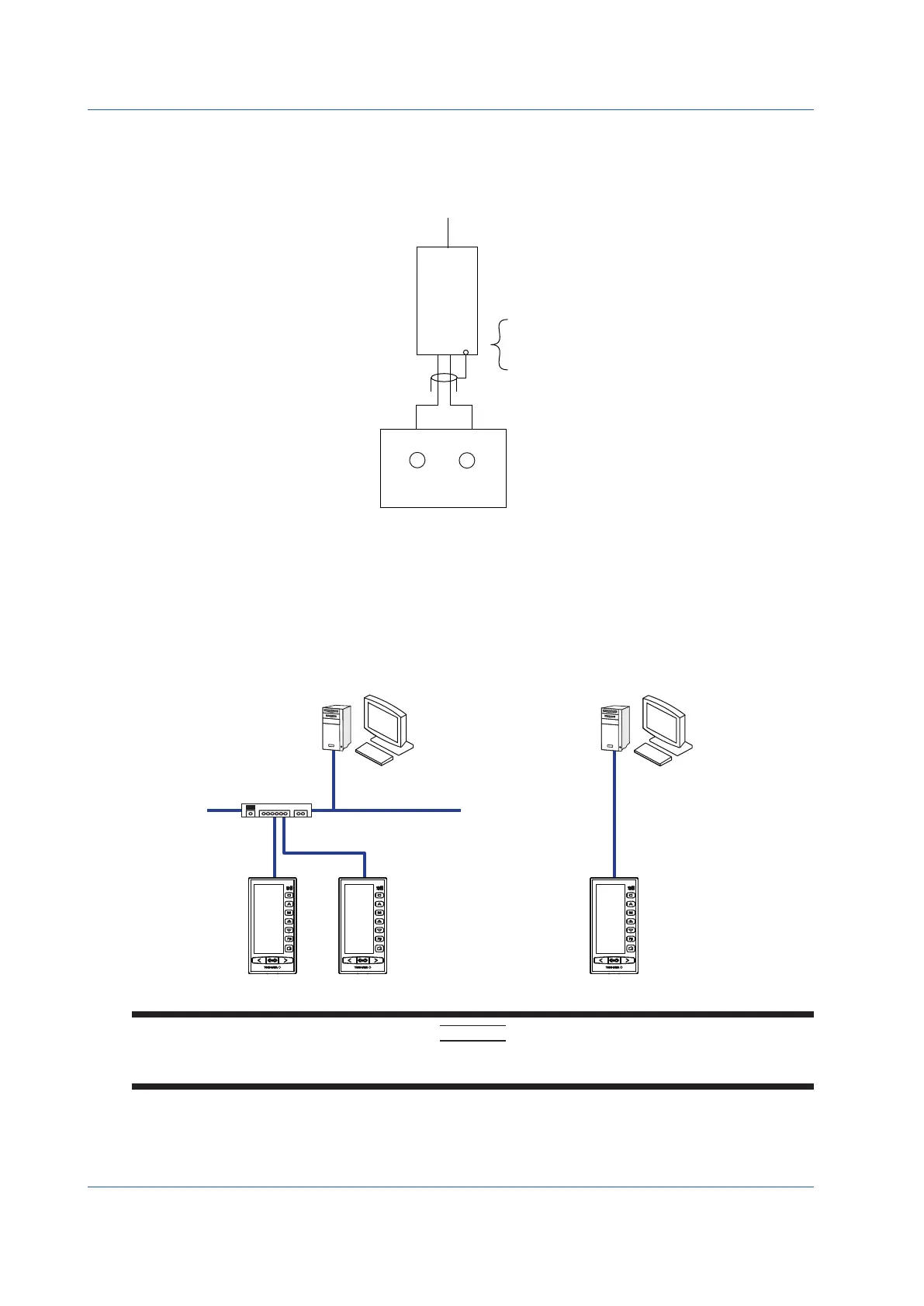
Wiring for the Ethernet Communication Interface (Optional Code /A34)
Ethernet
HUB
Straight cable Cross cable
Device that can be
connected over Ethernet
Device that can be
YS1000 YS1000 YS1000
CAUTION
Ifthereisanyriskofasurgeduetolightningdischarge,anarresterforEthernet(100BASE-TX/10BASE-T)shouldbe
connected.

 Loading...


