32
IM 01B08B02-01EN
32
Operating the Tuning Displays
There are displays for setting and displaying control parameters such as PID, etc. and a display for monitoring input/output sig-
nals. To set tuning parameters proceed according to the setting examples below, and refer to “Overview of Display Switching and
Operation Keys” and “List of Parameters”.
► Fordisplayingandsettingparameters:see“ListofParameters”inthismanual.
► Foradescriptionoftuningparameterfunctions:seeYS1500IndicatingController/YS1700ProgrammableIndicatingControllerUser’sManual.
Note
YS1000 has a password function as a security function. If the password has been set up, enter it and then change
parameters.
► Forsettingandcancelingpasswords:see4.2.2,Inhibiting/EnablingParameterChange,intheYS1500IndicatingController/YS1700Program-
mable Indicating Controller User’s Manual.
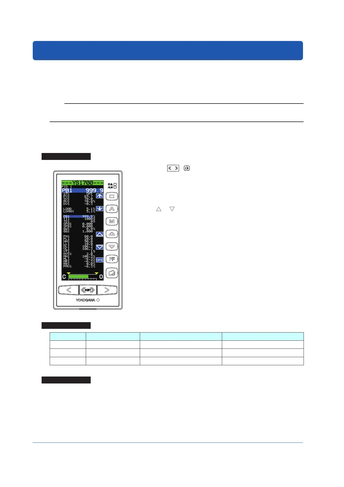
Setting PID
Setting Display
Tuning Display
Operation Display >
SHIFT
+ keys (to the Tuning Menu Display) > [PID1] software key
(PID Setting Display 1) or [PID2] software key (PID Setting Display 2)
Setpoint changing procedure (example of changing proportional band 1):
(1) Pressthe[↓]softwarekeytoselectandzoominonproportionalband1[PB1
999.9%].
(2) Press the [ ] or [ ] software key to change the setpoint. Holding it down
accelerates the value increase/decrease speed.
(3) Press the Page key to return to the Tuning Menu Display.
(4) Press the SHIFT + Page keys twice to return to the Operation Display.
This completes the setting procedure.
Setting Details
Parameters Names Setting Range Factory Default
PB1, PB2 Proportional band 0.1 to 999.9 (%) 999.9
TI1, TI2 Integral time 1 to 9999 (s) 1000
TD1, TD2 Derivative time 0 to 9999 (0: no action) 0
Description
The PB2, TI2, and TD2 parameters are used in the loop 2 in the cascade mode, selector mode, and programmable mode.
► Forproportionalband,integraltime,andderivativetime:see“TuningGuide”inthismanual.

 Loading...


