33
IM 01B08B02-01EN
Operating the Tuning
Displays
Operating the Tuning Displays
Displaying the Operation Display While the Tuning Display is being Shown
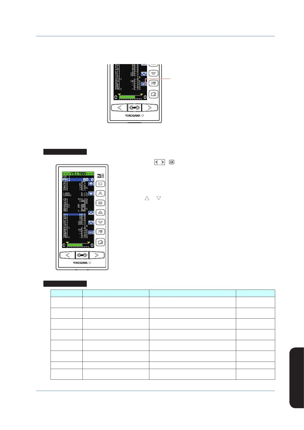
Pressing the [OPE] software key while setting a tuning parameter returns you to the Operation Display.
Tuning Display
[OPE] software key
0602E.ai
Setting Alarms
Setting Display
Tuning Display
Operation Display >
SHIFT
+ keys (to the Tuning Menu Display) > [PID1] software key
(PID Setting Display 1) or [PID2] software key (PID Setting Display 2)
Setpoint changing procedure (example of changing high limit alarm setpoint for PV1)
(1) Pressthe[↓]softwarekeytoselectandzoominonhighlimitalarmsetpointforPV1
[PH1 106.3].
(2) Press the [ ] or [ ] software key to change the setpoint. Holding it down
accelerates the value increase/decrease speed.
(3) Press the Page key to return to the Tuning Menu Display.
(4) Press the SHIFT + Page keys twice to return to the Operation Display.
This completes the setting procedure.
Setting Details
Parameters Names Setting Range Factory Default
PH1, PH2 High limit alarm setpoint for PV
Engineeringunitsequivalentto−6.3to106.3%
(*1)
106.3
PL1, PL2 Low limit alarm setpoint for PV
Engineeringunitsequivalentto−6.3to106.3%
(*1)
-6.3
HH1, HH2 High-high limit alarm setpoint for PV
Engineeringunitsequivalentto−6.3to106.3%
(*1)
106.3
LL1, LL2 Low-low limit alarm setpoint for PV
Engineeringunitsequivalentto−6.3to106.3%
(*1)
-6.3
DL1, DL2 Deviation alarm setpoint
Engineering units equivalent to 0.0 to 106.3%
(*1)
0.0
VL1, VL2 PV velocity alarm setpoint
Engineering units equivalent to 0.0 to 106.3%
(*1)
0.0
VT1, VT2 PV velocity alarm time setpoint 1 to 9999 1
HYS1, HYS2 Alarm hysteresis
Engineering units equivalent to 0.0 to 20.0%
(*1)
2.0
*1 Engineering unit set using the engineering parameters SCH1, SCL1, and SCDP1 (or SCH2, SCL2, and SCDP2).

 Loading...


