Do you have a question about the YOKOGAWA UP55A and is the answer not in the manual?
Easily sets basic controller functions for immediate operation.
Describes PV, control, and remote input functions, including universal input and output types.
Details the UP55A's five control modes: single-loop, cascade, loop control with PV switching, and PV auto-selector.
Explains the functions for creating and executing program patterns with segments, ramps, and time events.
Covers active color PV display, guide display, multilingual options, and user function keys.
Describes the use of the ladder sequence function requiring LL50A Parameter Setting Software for programming.
Covers RS-485, Ethernet, PROFIBUS-DP, DeviceNet, and CC-Link communication interfaces.
Outlines the flow from unpacking to regular operation, including setup and initial configuration.
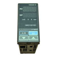
Identifies and describes the various display components and indicators on the UP55A's front panel.
Explains the purpose and operation of each key on the UP55A's front panel for navigation and control.
Provides a comprehensive list of symbols used in the PV display, symbol display, and data display areas.
Explains parameter symbols, names, display levels, setting ranges, and menu symbols for configuration.
Illustrates the display transitions between operation, parameter setting, and setup modes using the controller's keys.
Provides a step-by-step guide on how to set various parameters, using alarm setpoint as an example.
Details how to use the quick setting function for initial setup of control type, input, and output functions.
Explains methods to restart the quick setting function after initial setup for parameter re-configuration.
Describes operation display transitions for single-loop, cascade, and loop control modes with PV switching/auto-selector.
Details the operation display transitions specific to cascade control configurations.
Explains the types of operation displays and their corresponding operation descriptions for various functions.
Guides on how to perform and cancel auto-tuning for PID control parameter optimization.
Explains the procedure for manually tuning PID parameters like proportional band, integral time, and derivative time.
Details how to set alarm setpoints for various alarm types, including PV, SP, and deviation alarms.
Explains how to select the program pattern number for execution using PTN key or operation mode parameter.
Details how to switch between different operation modes like PROG, RESET, LOCAL, REMOTE, HOLD, ADVANCE, AUTO/MAN.
Explains how to select the starting segment number for program operation using MODE key or operation mode parameter.
Describes how to fast-forward program patterns to check settings, affecting segment and time events.
Details how to change setpoints (SP, TSP) and segment time (R.TIM) while the program is in HOLD mode.
Explains how to change the program pattern during operation via parameter setting, with changes reflected in the next operation.
Covers methods to control output value during manual operation using direct keys or SET/ENT key.
Explains how to release latched alarm outputs using user function keys, communication, or contact input.
Covers setting input types, units, ranges, scales, and decimal point positions for various analog inputs.
Details how to set the input sampling period, also known as the control period, for the controller.
Explains how to use a 4-wire RTD as PV input, requiring specific suffix codes for remote or PV input.
Explains how to use PV auto-selector to select or calculate values from multiple inputs for control.
Describes the two methods for remote input: analog input via RSP terminal or remote setting via communication.
Details how to set the PV range for control when input signals have different measurement ranges.
Describes methods for switching PV inputs based on contact input or temperature range.
Details the available control modes including single-loop, cascade, and loop control with PV switching/auto-selector.
Explains combinations of control types (PID, ON/OFF, Heating/cooling) with control modes and output types.
Covers methods for switching PID parameters based on target setpoint, PV, deviation, or local PID selection.
Explains the Super function for monitoring deviation and automatically adjusting setpoint to prevent overshoot.
Describes the Super2 function to suppress controller hunting without re-tuning PID parameters.
Explains the anti-reset wind-up function to prevent extreme integral output by stopping PID computations.
Details performing non-linear PID control, adjusting proportional band and gain for smooth output changes.
Guides on setting auto-tuning type (normal/stable) and output limits for PID constant optimization.
Describes setting SP high and low limits to restrict the SP to the operating range between those limits.
Explains setting the program time unit for segment time, ramp-rate, wait time, time event, and start time.
Details the SP tracking function to force local setpoint to track program or remote setpoint when switching to local mode.
Explains how to set the controller's action upon power recovery, including continuing previous action or starting from MAN/RESET.
Allows setting the time between controller power-on and the start of control computation.
Explains how to set program patterns using segment time or ramp-rate criteria.
Covers segment PID number selection and zone PID selection methods for automatic PID switching.
Details methods for starting program operations based on initial setpoint, PV, or time.
Explains program wait functions at segment end and in the middle of a segment, including wait zones and times.
Describes how to set repeat functions to repeat successive segments multiple times within a program pattern.
Explains the pattern-link function to link multiple patterns and run them as a single program pattern.
Covers setting event functions for outputting alarms or activating contact outputs based on PV or time.
Describes how the controller switches between segments, including continuation, hold, local, remote, and advance operations.
Explains creating a program pattern for retransmission to a slave controller on the same timeline and target setpoint.
Details setting the time delay from program operation start (RUN) to the start of the program pattern.
Describes the function to reset the program pattern number in Operation Display to 0 when the program operation ends.
Explains how a pattern end signal notifies the outside of the program pattern execution completion via contact output or communication.
Covers checking remaining segments, copying, adding, deleting, and listing error codes for program patterns.
Details synchronized operation during segment switching and program pattern progression using wait and contact I/O.
Explains how to set control output types for relay, triac, voltage pulse, current, and position proportional outputs.
Details setting the basic cycle period for ON/OFF operation of relay/triac or voltage pulse outputs.
Describes how to set high and low limits to restrict the control output within a specific operation range.
Explains how to release the output limiter when the controller is in MAN mode.
Covers setting output velocity limit to prevent sudden changes in control output signal.
Explains the tight shut function to fully close the control valve beyond its positioner dead band.
Explains how to set hysteresis for ON/OFF control to prevent relay chattering and ensure service life.
Describes using manual reset to cancel offset when the integral action is disabled.
Details setting hysteresis and dead band for heating/cooling control outputs in ON/OFF or PID modes.
Explains setting hysteresis and dead band for position proportional control output to prevent frequent motor operation.
Covers setting retransmission output terminals (RET, OUT, OUT2), types, and scales for PV, SP, or output values.
Details setting preset output values for different modes like RESET, MAN, and AUTO, including heating/cooling control.
Explains using 10-segment linearizers for output to correct non-linear relationships or apply bias/approximation.
Describes how to select and change the analog output type for current signals (4-20mA, 0-20mA, etc.).
Explains the split computation output function for linking multiple operating units with V-mode or Parallel-mode characteristics.
Covers adjusting valve position manually or automatically for position proportional control.
Details the function of the 15 V DC loop power supply for 2-wire transmitters and its connection.
Details various alarm types including PV, SP, deviation, output, and analog input limits with their actions.
Explains how to set the number of available alarm groups, and how unused parameters can be hidden.
Explains how to set hysteresis to alleviate busyness of alarm output switching.
Describes the function of on-delay and off-delay timers for alarm outputs.
Explains how to use control relay terminals for alarm output when not used for control output.
Details how to set the alarm mode to disable alarm action in RESET or MAN mode.
Covers setting heater break alarm function, including current measurement and timing.
Explains how to set contact input numbers to functions like operation mode, auto-tuning, and program pattern selection.
Describes how to assign status such as alarms to contact outputs and set their action direction.
Covers active color PV display, guide display, multilingual options, and parameter display level settings.
Explains how to assign functions like operation mode switch to the user function keys on the front panel.
Details setting passwords, locking parameter menus, and prohibiting writing via communication.
Describes how to confirm the status of keys, I/O conditions, and controller version information.
Explains how to initialize all parameter settings and the ladder program to factory default values.
Describes how to register and initialize user-defined default values for parameters, excluding ladder and program patterns.
Outlines controller behavior and remedies based on the duration of power failure, affecting alarm, auto-tuning, and control action.
Details how to set the power frequency manually or via automatic detection, with manual setting for /DC option.
Provides a flowchart and tables for diagnosing and resolving errors during power on and operation.
Covers cleaning procedures, packaging for repair, and replacing parts (not recommended).
Recommends periodically checking the operating condition for optimal instrument performance.
Provides guidance on arranging for appropriate disposal as industrial waste according to local regulations.
Specifies conditions for proper instrument installation, including ventilation, vibration, and environmental factors.
Details the procedure for mounting the instrument main unit onto a panel, including bracket installation and torque specifications.
Provides dimensional drawings for the UP55A, including panel cutout dimensions for installation.
Provides essential information and diagrams for wiring various inputs, outputs, and communication interfaces.
Provides a comprehensive overview of parameter organization, group display, and display levels.
Lists and describes all available parameters categorized by menu, including initial values and setting ranges.
| Model | UP55A |
|---|---|
| Type | Controller |
| Control Method | PID control |
| Input Type | Thermocouple, RTD, DC voltage, DC current |
| Alarm Output | Relay contact |
| Dimensions | 96 x 96 x 100 mm |
| Operating Temperature | 0 to 50 °C |
| Storage Temperature | -20 to 60 °C |
| Display | LED digital display |
| Communication Protocols | RS-485 |
| Communication | Ethernet |
| Power Supply | 100-240V AC |
| Control Output | Relay contact, voltage pulse, current |
| Power Consumption | 10W |