17-12
IM 05P02C41-01EN
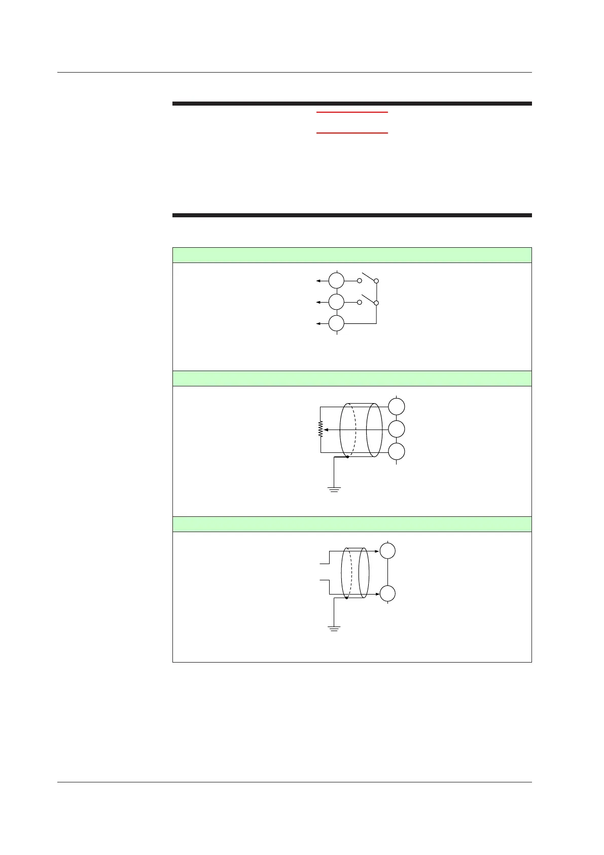
17.4.5 ValvePositionOutputandFeedbackInputWiring
CAUTION
1) Use an auxiliary relay for load-switching if the contact rating is exceeded.
2) Keep the relay output wires and the feedback input wires at least 30 cm apart.
3) The output relay has a limited service life. Be sure to connect a CR filter (for AC)
or diode (for DC) to the load.
4) If there is a risk of external lightning surges, use a lightning arrester etc.
5) This should always be used with a load of 10 mA or more.
► Whenusingauxiliaryrelay:17.4.4ControlOutput(Relay,Current,andVoltagePulse)Wiring
Relaycontactoutput
507
508
509
VALV
HIGH
(direct)
LOW
COM
Contact rating: 250 V AC, 3 A
30 V DC, 3 A (resistance load)
Note: This should always be used with a load of 10 mA or more.
Feedback input (resistor)
100%
0%
510
511
512
VALV
Shield
Resistance:
100
Ω to 2.5 k
Ω
Feedback input (current)
510
512
VALV
4 to 20 mA DC
–
+
Grounding
*: Always set the terminal 511 in open state.
17.4Wiring

 Loading...


