1-10
IM 05P02C41-01EN
1.7 CommunicationFunctions
The UP55A can use RS-485 communication, Ethernet communication, PROFIBUS-DP
communication, DeviceNet communication, and CC-Link communication by specifying
the suffix code and optional suffix code for each communication.
► UTAdvancedSeriesCommunicationInterface(RS-485,Ethernet)User’sManual
► UTAdvanced Series Communication Interface (Open Network) User’s Manual
RS-485Communication(Modbuscommunication,PClinkcommunication,and
Ladder communication)
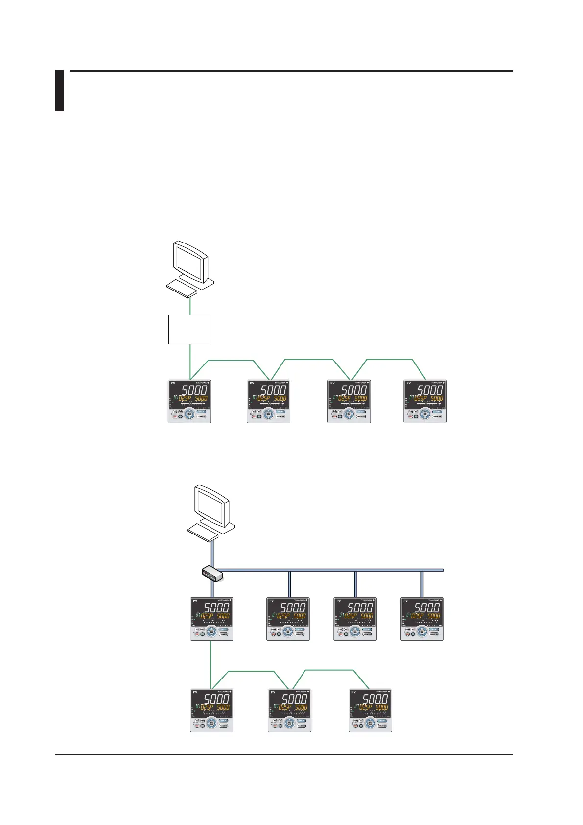
The UP55A can communicate with PCs, PLCs, touch panels, and other devices.
Up to 31 connected slaves with a maximum length of 1200m
Model: ML2 of YOKOGAWA is recommended.
RS-232C/
RS-485
converter
Ethernet Communication (Modbus/TCP)
The UP55A can be connected to IEEE802.3-compliant network (10BASE-T/100BASE-
TX).Aserialgatewayfunctioncanincreasethenumberofconnectedcontrollers.
Ethernet
Modbus/RTU
Modbus/TCP
Host computer
Hub
LAN
Distance from hub to controller: Within 100 m
Number of cascade connections on hub:
Max. 4 stages (10BASE-T)
Max. 2 stages (100BASE-TX)
RS-485 communication
Serial gateway function
Up to 31 connected slaves with a maximum length of 1200m

 Loading...


