Do you have a question about the YOKOGAWA UT550 and is the answer not in the manual?
Guidance on navigating and utilizing the sections of this user manual for effective operation.
General safety warnings, symbols, and policy disclaimers for safe operation and handling of the controller.
Guidelines for mounting, wiring, and understanding hardware specifications for controller installation.
Visual diagrams illustrating the terminal connections for various controller functions and models.
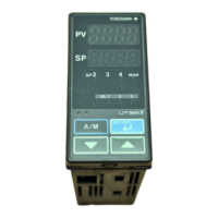
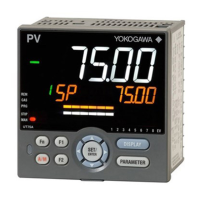
Identification of front panel components and overview of initial setup steps.
Steps for setting PV input type, range, and control output type.
Procedures for resetting parameters, changing alarm types, and setting alarm setpoints.
Explanation of multiple setpoints, PID parameters, and their selection methods.
Overview of operating displays and procedures for setting target setpoints and performing auto-tuning.
Procedures for switching control modes (RUN/STOP, AUTO/MAN, REM/LCL) and manipulating output manually.
Flowcharts, error codes, and procedures for diagnosing and resolving controller operational issues.
Guidance on cleaning, replacing parts like brackets, terminal covers, and control output relays.
Introduction to parameter maps and overview of operating and setup parameter structures.
Detailed explanations of parameters for setpoints, alarms, control, inputs, outputs, and modes.
Block diagrams illustrating signal flow for single-loop control types.
Explanation of functions for remote input, contact input, setpoints, PID, control output, and retransmission.
| Model | UT550 |
|---|---|
| Input Type | Thermocouple, RTD, DC Voltage, DC Current |
| Number of Loops | 1 |
| Control Method | PID Control |
| Output Type | Relay, Voltage, Current |
| Display | LCD |
| Power Supply | 100 to 240 VAC |
| Communication Protocols | RS-485 |
| Dimensions | 96 x 96 x 100 mm |
| Measurement Range | Depends on input type |