<Toc> < 5. Parameters >
5-15
IM 05D01C02-41E 3rd Edition: May 31, 2006-00
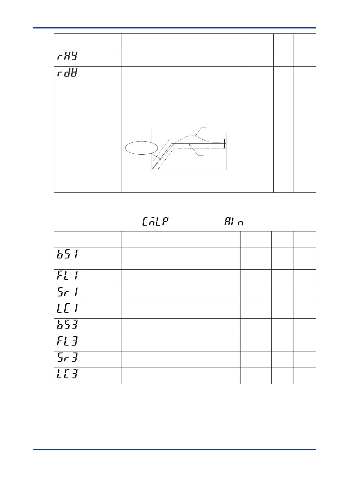
Used to select a group of PID parameters according to a deviation from
the given target setpoint. The controller uses the PID parameters of the
number selected in PID group number (GRP) if the PV input falls outside
the given deviation range.
The following example shows a case when only the reference deviation
is set without setting any reference point. The selected set of PID
parameters is as follows.
Since region 1 is within the deviation range, the controller uses the 1st
group of PID parameters.
Since region 2 is outside the deviation range, the controller uses the
PID parameters of the number selected in PID group number (GRP).
OFF (0): Disable
0.0% to 100.0% of PV input range span
(RHY)
(RDV)
Reference deviation (RDV)
Maximum value of
PV input range
RH1
RL1
Minimum value of
PV input range
Target setpoint
PV input value
Reference deviation (RDV)
[1]
[2]
[2]
[1]
[1]
[2]
A slope is set to vary
the target setpoint.
Zone switching
hysteresis
Reference deviation
0.0 to10.0% of PV input range span
Allows hysteresis to be set for switching at a reference point.
0.5% of PV
input range
span
OFF (0)
Parameter
Symbol
Name of Parameter Setting Range and Description Initial Value User
Setting
Target Item
in CD-ROM
Same as
above
Same as
above
● Analog Input Computation Parameters
Located in: Main menu =
(CMLP)
; Submenu =
(AIN)
Parameter
Symbol
Name of Parameter Setting Range and Description Initial Value User
Setting
Target Item
in CD-ROM
Analog input-1 bias Used to correct the PV input value beforehand.
When in normal operation, use the PV Input Bias (BS) operating
parameter.
-100. 0% to 100.0% of PV input range span
0.0% of PV
input range
span
Analog input-1 filter OFF (0): Disable
1 to 120 sec.
OFF (0)
(FL1)
(BS1)
Analog input-1
square-root
computation
Performs square-root computation for the PV input value.
OFF (0): Do not compute the square root
ON (1): Compute the square root
OFF (0)
Analog input-1 low
signal cutoff
0.0% to 5.0%
The slope equals “1” at levels below the low-signal cutoff point.
1.0%
(LC1)
(SR1)
Analog input-3 bias Used to correct the remote input value.
-100. 0% to 100.0% of PV input range span
0.0% of PV
input range
span
Analog input-3 filter OFF (0): Disable
1 to 120 sec.
OFF (0)
(FL3)
(BS3)
Analog input-3
square-root
computation
Performs square-root computation for the remote input value.
OFF (0): Do not compute the square root
ON (1): Compute the square root
OFF (0)
Analog input-3 low
signal cutoff
0.0% to 5.0%
The slope equals “1” at levels below the low-signal cutoff point.
1.0%
(LC3)
(SR3)
Ref.1.1(6)
Ref.1.1(3)
Ref.1.1(6)
Ref.1.1(3)
Ref.1.2(2)
Same as
above
Same as
above
Same as
above
Same as
above
 Loading...


