6-6
<Toc> < 6. Function Block Diagram and Descriptions >
IM 05D01C02-41E 3rd Edition: May 31, 2006-00
■ Remote Input
Remote input (INPUT3) can receive DC voltage signals. The controller is capable of
biasing, square root extraction, first-order lag computation (filtering), and ratio biasing on
remote input signals.
Each function can be set by the following parameters.
Setup Parameters
Function Parameter Main menu Submenu
Input selection IN3 UTMD IN
Unit selection UN3 UTMD IN
Analog input range conversion RH3, RL3 (DP3, SH3, SL3) UTMD IN
Analog input bias BS3 CMLP AIN
Square root extraction SR3, LC3 CMLP AIN
Analog input filter FL3 CMLP AIN
Remote input selection RMS LOOP1 SP
Note: Remote input signal can be received via communication. For details, refer to “GREEN Series Communication
Functions” (IM 05G01B02-01E).
Operating Parameters
Function Parameter Main menu Submenu
Remote setting filter RFL LP1 PAR
Ratio bias calculation RT, RBS LP1 PAR
Remote/Local switching MOD(REM/LCL) MODE None
■ Contact Input
Automatic (ON) / Manual (OFF) switching function is assigned to DI1 (contact input 1).
Manipulated output can be changed using the
and key in manual mode.
Run (OFF) / Stop (ON) switching function is assigned to DI2 (contact input 2). Preset
output value is output when the operation is stopped. PV input and alarms remain function-
ing as normal.
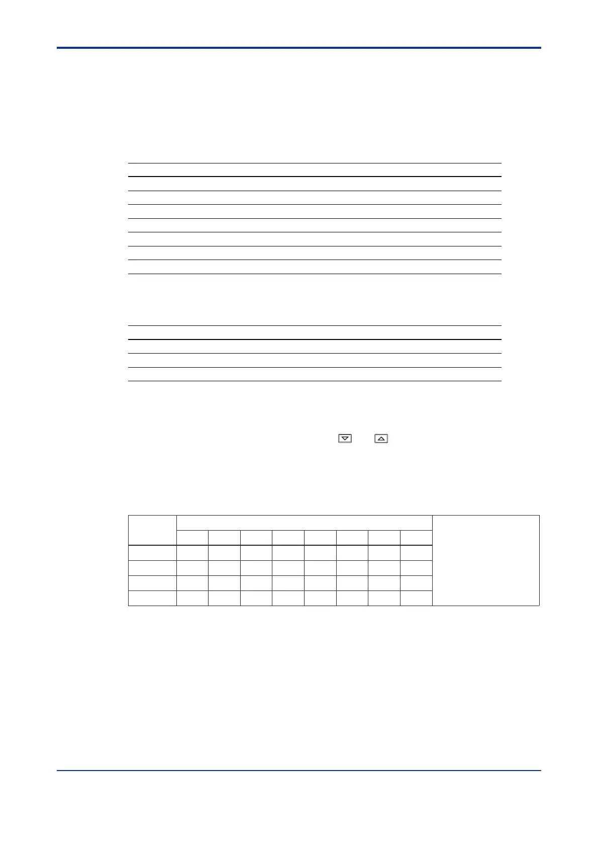
It is possible to select one out of eight setpoints by turning the four contact input signals ON
or OFF. This function is assigned to DI3 (contact input 3) to DI6 (contact input 6).
8
DI3 OFF
DI4 OFF
DI5 OFF
DI6 ON
Selected target setpoint number If all contact inputs
are set to “OFF”, the
controller uses the
immediately preceding
target setpoint.
7
ON
ON
ON
OFF
6
OFF
ON
ON
OFF
5
ON
OFF
ON
OFF
4
OFF
OFF
ON
OFF
3
ON
ON
OFF
OFF
2
OFF
ON
OFF
OFF
1
Contact
input
ON
OFF
OFF
OFF
For example, set contact input 4 (DI4) only to “ON” to change target setpoint 1 to 2. Set contact inputs 3 (DI3) and 4 (DI4) to
“ON” to select target setpoint 3.
No function is assigned to DI7 (contact input 7).
Remote/Local mode switching function is assigned to DI8 (contact input 8). External target
setpoint can be set via remote input (INPUT3).
 Loading...


