5-2
<Toc> < 5. Parameters >
IM 05D01C02-41E 3rd Edition: May 31, 2006-00
SPN
MOD
(R/L)
MOD
(C.A.M)
SET3S
MODE LP1
Operating display
Operating
display 1
Main menu
Submenu
LP2
*4
Operating
display 2
1.A3
1.A2
1.A1
1.SP
1.I
1.P
1.A4
1.OH
1.D
1.MR
1.OL
1.H
1.Pc
1.DR
1.Ic
1.Hc
1.Dc
1.DB
1.Oc
1.PO
7.A3
7.A2
7.A1
7.SP
7.I
7.P
7.A4
7.OH
7.D
7.MR
7.OL
7.H
7.Pc
7.DR
7.Ic
7.Hc
7.Dc
7.DB
7.Oc
7.PO
1.PID
Not displayed for
ON/OFF control
Displayed for
heating/cooling
control
Displayed for
heating/cooling, position
proportional control
Displayed for
heating/cooling control
Not displayed for
heating/cooling control
8.A3
8.A2
8.A1
Same
as LP1
8.SP
8.I
8.P
8.A4
8.OH
8.D
8.MR
8.OL
8.H
8.Pc
8.DR
8.Ic
8.Hc
8.Dc
8.DB
8.Oc
8.PO
SET
BS
SC
AT
DNR
UPR
FL
RBS
RT
ORB
RFL
ORH
ORL
SET
PAR
MOD
(S/R)
SET
SET SET
+
+
*1
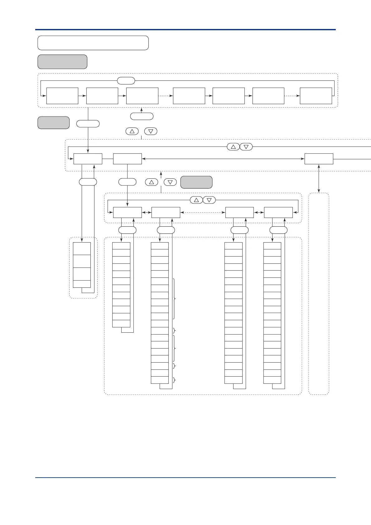
*1 Parameter MOD (C.A.M.) is displayed when UT mode is “Cascade secondary-loop control”, or “Cascade control.”
*2 Parameter MOD (R/L) is displayed only for the controller with auxiliary analog (remote) input.
*3 Parameter MOD (S/R) is displayed when parameter S/R for registering contact input (setup parameter) is “0.”
*4 Main menu LP2 is displayed when UT mode is “Cascade control.”
*5 Main menu USR is displayed when UT mode is “Loop control with PV switching”, or “Loop control with PV auto-selector.”
*6 Main menu PYS2 is displayed when UT mode is “Cascade control.”
*2
*3
Operating
display 3
Operating
display n
SELECT
display 1
SELECT
display 2
SELECT
display 5
SET3S
or
8.PID
SET SET
7.PID
UT550/UT520 Operating Parameter Map
 Loading...


