5-24
<Toc> < 5. Parameters >
IM 05D01C02-41E 3rd Edition: May 31, 2006-00
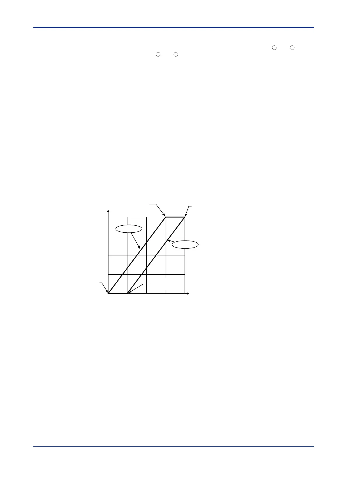
● Parallel-mode Output
The following explains an example of letting “Analog OUTPUT-1 (terminals
16
and
17
)” and
“Analog OUTPUT-3 (terminals
14
and
15
)” present the parallel-mode characteristics of split
computations.
1. Set the Control Output Type (OT1) parameter to “2”.
This sets the control output to “current output.”
2. Set the Retransmission Output 1 (RT1) parameter to “3”.
This sets the retransmission output to “control output retransmission.”
3. Set the Analog Output-1 100% Segmental Point (A1H) parameter to “100%”.
4. Set the Analog Output-1 0% Segmental Point (A1L) parameter to “25%”.
5. Set the Analog Output-3 100% Segmental Point (A3H) parameter to “75%”.
6. Set the Analog Output-3 0% Segmental Point (A3L) parameter to “0%”.
The figure below shows an example where both analog outputs-1 and 3 are set to the
current signal of 20 to 0 mA DC. The type of output signal can be determined separately
for each of the analog outputs listed above, using the following three parameters.
Analog output-1: Analog output-1 type (AO1)
Analog output-2: Analog output-2 type (AO2)
Analog output-3: Analog output-3 type (AO3)
05025 75 100
25
50
75
100
%
%
0
mA
20 0
10
15
5
Output value before split computation
Output value after computation
Analog output-1
100% segmental
point (A1H)
Analog output-3
100% segmental
point (A3H)
Analog output-3
0% segmental
point (A3L)
Analog output-3
Analog output-1
Analog output-1
0% segmental
point (A1L)
 Loading...


