<Toc> < 1. Installation >
1-1
IM 05D01C02-41E 3rd Edition: May 31, 2006-00
1. Installation
This chapter describes installation, wiring, and other tasks required to make the
controller ready for operation.
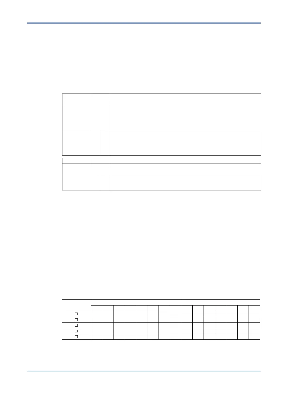
1.1 Model and Suffix Codes
Before using the controller, check that the model and suffix codes match your order.
Model Suffix Code Description
UT550
Digital indicating controller (provided with retransmission output and 15 VDC loop power supply as standard)
-0 Standard type
-1 Position proportional type
-2 Heating/cooling type
-3 Standard type (with 24 V DC loop power supply)
Type
-4 Position proportional type (with 24 V DC loop power supply)
0
1
2
3
Optional functions
4
Model Suffix Code Description
UT520
Digital indicating controller (provided with retransmission output and 15 VDC loop power supply as standard)
Type -0 Standard type
0 None
7 With communication, auxiliary analog (remote) input, and 2 additional DIs
Optional functions
8 With auxiliary analog (remote) input and 2 additional DIs
None
With communication, auxiliary analog (remote) input, 6 additional DIs and 4 additional DOs
With communication, auxiliary analog (remote) input, and 1 additional DI
With 5 additional DIs and 4 additional DOs
With auxiliary analog (remote) input and 1 additional DI
Check that the following items are provided:
• Digital indicating controller (of ordered model): ........................................... 1
• Brackets (mounting hardware): .................................................................. 1 pair
• Unit label:................................................................................................... 1
• User’s Manuals for Single-loop Control: ..................................................... 5 (A2 size)
• User’s Manual (Reference) (CD-ROM Version): ......................................... 1
■ Correspondence between the Model and Suffix Codes, and the Contact
Input/Output Terminals Provided
Check the model ordered and the presence/absence of contact inputs and outputs in the
following table.
✓ indicate that the contacts are available.
Contact input terminals Contact output terminals
Model and Suffix
Codes
DI1 DI2 DI3 DI4 DI5 DI6 DI7 DO1 DO2 DO3 DO4
UT550- 1
UT550- 0
UT550- 2
UT550- 3
UT550- 4
DI8 DO5 DO6 DO7
✓
✓
✓
✓
✓
✓
✓
✓
✓
✓
✓
✓
✓
✓
✓
✓
✓
✓✓
✓
✓
✓
✓
✓
✓
✓
✓
✓
✓
✓
✓
✓
✓
✓
✓
✓
✓
✓
✓
✓
✓
✓
✓
✓
✓
✓
Note: For details on the functions of contact inputs/outputs, see “1.5 Terminal Wiring Diagrams” .
✓ indicate that the contacts are available.
 Loading...


