Do you have a question about the YOKOGAWA UT350 and is the answer not in the manual?
Explains the purpose, title, and description of each section of the manual.
Provides guidelines and disclaimers for using the user's manual.
Explains the meaning of key safety symbols like CAUTION, NOTE, and IMPORTANT.
Outlines Yokogawa's limitations of liability and terms of use for software.
Describes how to check model and suffix codes to match the order.
Lists criteria for selecting a suitable installation location for the controller.
Describes the procedure for installing the controller into a panel.
Advises turning off power and checking cables before wiring.
Provides guidance on power supply, noise, and wire types for safe wiring.
Details specifications for PV input signals, including type, sampling, and resistance.
Describes specifications for the loop power supply, including voltage and current.
Details specifications for the current output type.
Details specifications for the voltage pulse output type.
Details specifications for the relay contact output type.
Describes the construction, material, weight, and dimensions of the controller.
Mentions the panel-mounting type and hardware.
Lists ambient temperature, humidity, vibration, and other environmental limits.
Specifies temperature, change rate, and humidity for storage and transport.
Warns against using unassigned terminals as relay terminals.
Shows wiring for various PV input types.
Shows wiring for control output and retransmission.
Details how DIS and OT parameters map to functions.
Shows wiring for heating-side control output.
Shows wiring for cooling-side control output.
Shows wiring for alarm outputs and retransmission.
Shows wiring for control output and retransmission.
Shows wiring for PV input and power supply.
Shows wiring for heating and cooling control outputs.
Shows wiring for alarm outputs and retransmission.
Outlines the sequence of steps for initial controller setup.
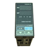
Lists and describes the function of each part on the controller's front panel.
Shows factory-set default values for main parameters.
Explains what 'IN' means and how to set PV input type at power-on.
Shows examples of setting PV input range for temperature and voltage.
Provides a table of instrument input types, codes, ranges, and accuracies.
Shows terminal assignments for different PV input types.
Guides on changing the PV input type from K-type to Pt 100.
Details registering setpoints and returning to the operating display.
Lists terminal assignments for different control output types.
Guides on changing the control output type to current output.
Lists terminal assignments for alarm outputs and their factory defaults.
Guides on changing alarm-1 type from PV high limit to PV low limit.
Details registering alarm type setpoints and returning to operating display.
Provides a table of alarm types, actions, and corresponding codes.
Illustrates controller behavior regarding alarm output based on PV and setpoint.
Warns against strong magnetic fields near the controller causing PV fluctuation.
Describes the SP display and OUT display for standard controllers.
Describes the SP and OUT displays for standard controllers.
Describes SP and output displays for heating/cooling controllers.
States that target setpoint cannot be changed via keystroke when set by communication.
Guides on setting the target setpoint value via keystrokes.
Lists conditions and processes where auto-tuning cannot be performed.
Guides on performing and canceling the auto-tuning function.
Guides on manually setting PID parameters like proportional band.
Lists terminal assignments for alarm outputs and their factory defaults.
Guides on setting alarm setpoint values.
Notes on contact input switching and PV tracking for target setpoint selection.
Guides on changing the target setpoint number.
Explains the need to configure the DIS parameter for RUN/STOP switching.
Details PV input, control output, and alarm output behavior when stopped.
Notes that AUTO/MAN switching via contact input prevents keystroke changes.
Explains the A/M key function for switching between AUTO and MAN modes.
States that control output cannot be changed if the controller is stopped.
Guides on changing the control output value in manual mode.
Describes how control output is manipulated for heating/cooling control.
Provides a flowchart for troubleshooting issues when the operating display does not appear.
Details power-on errors, their descriptions, and remedies.
Details possible errors occurring during operation and their remedies.
Explains that short power failures do not affect controller operation.
Describes controller behavior during longer power failures and recovery.
Guides on troubleshooting issues where PV is not displayed.
Guides on troubleshooting lack of control output or no change in output.
Guides on troubleshooting delayed control output changes after setpoint variation.
Describes how to clean the front panel and operation keys.
Provides information on purchasing and replacing mounting brackets.
Warns about touching terminals during power supply and checking power cable.
Explains how to fold and attach the terminal cover.
Introduces a table listing parts with limited service life and their expected service life.
Warns to turn off power before replacing relays to avoid electric shock.
Describes the initial steps for replacing control output relays.
Guides on removing the internal unit, locating relays, and inserting new ones.
Explains how to reinsert the internal unit and verify operation after replacement.
States that this chapter contains a parameter map for setting parameters.
Illustrates navigation through the operating and parameter displays.
Warns that changing setup parameters may initialize operating parameters.
Lists parameters related to control functions.
Lists parameters related to input/output functions.
Lists key operating parameters like communication, alarms, auto-tuning, and PID.
Lists parameters for PV input filtering, limits, hysteresis, and heater burnout.
Details parameters for PID control, including proportional, integral, and derivative terms.
Describes parameters for reference deviation and PID zone points.
Explains the auto-tuning function and the method used.
Describes auto-tuning when using Zone PID.
Explains how hysteresis affects target setpoints and alarm setpoints.
Explains the purpose and working conditions of the target setpoint ramp setting function.
Details the method for setting up Zone PID, including reference points.
Describes parameters for setpoint limits, alarm types, hysteresis, and delay timers.
Describes parameters for control output cycle time and preset output.
Describes PID control modes and Zone PID selection.
Lists parameters for communication setup like protocol, baud rate, and parity.
Lists and describes parameters related to PV input type, unit, range, scale, and burnout.
Describes the control output type parameter.
Describes the DI function selection parameter and its configurations.
Describes parameters for registering displays in the SELECT function.
Describes parameters for enabling key lock and setting a password.
Details how to set parameter numbers for the SELECT display feature.
Explains how computation results are split into heating/cooling signals.
Provides precautions for heating/cooling control, including band ratios and integral time.
States the conditions for setting cycle time based on control output type.
Illustrates on-to-off time ratios for different control output percentages at 10s cycle time.
States the chapter covers function block diagrams for standard and heating/cooling types.
Shows the PV input and RS485 communication blocks.
Shows blocks for manual operation, control computation, mode switching, and output limiting.
Shows blocks for power supply, control output, retransmission, and alarm functions.
Explains the symbols used in the function block diagram.
Shows the PV input and RS485 communication blocks.
Shows blocks for manual operation, control computation, mode switching, and output limiting.
Shows blocks for heating/cooling output, power supply, retransmission, and alarms.
Explains the symbols used in the function block diagram.
Describes the PV input function and its capabilities.
Lists setup and operating parameters for PV input, unit, and range.
Explains how to receive remote input via communication.
Describes the functions assigned to contact inputs based on DIS parameter settings.
Lists operating parameters for target setpoint number selection and PID settings.
Explains the purpose and working conditions of the target setpoint ramp setting function.
Lists setup parameters for control output type, cycle time, and preset output.
Explains how alarms are output via contact outputs and lists related parameters.
Lists setup parameters for retransmission output type and scale.
Lists setup parameters for the 15V DC loop power supply.
| Brand | YOKOGAWA |
|---|---|
| Model | UT350 |
| Category | Controller |
| Language | English |