5-10
<Toc> <5. Parameters>
IM 05D01D02-41E 4th Edition: May 31, 2006-00
■ Setup Parameters
● Control Function-related Parameters
Alarm-1 type 1
Alarm-2 type 2
Alarm-3 type 1
OFF (0), 1 to 25, 28 to 31
1: PV high limit (energized, no stand-by action)
2: PV low limit (energized, no stand-by action)
3: Deviation high limit (energized, no stand-by action)
4: Deviation low limit (energized, no stand-by action)
5: Deviation high limit (de-energized, no stand-by action)
6: Deviation low limit (de-energized, no stand-by action)
These Alarm Type parameters are common to the
parameters 1.SP to 4.SP.
See “2.5 Changing Alarm Type” for other alarm types.
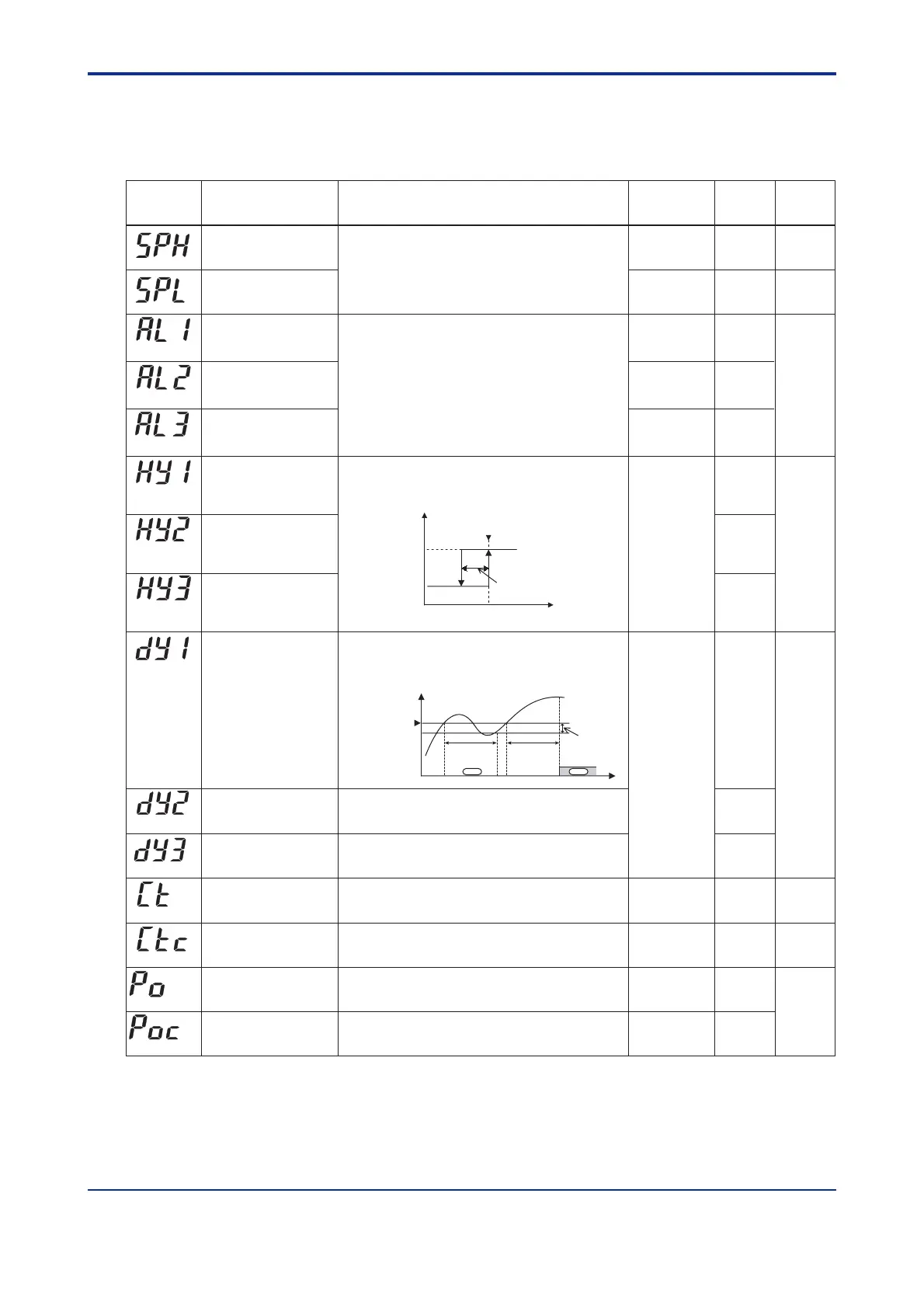
Alarm-1 hysteresis
Alarm-2 hysteresis
Alarm-3 hysteresis
Alarm-1 delay timer
Alarm-2 delay timer
Alarm-3 delay timer
0.0 to 100.0% of PV input range span
Output alarm: 0.0 to 100.0%
0.5% of PV
input range span
Output alarm:
0.5%
An alarm is output when the delay timer expires after the
alarm setpoint is reached.
0.00 to 99.59 (min, sec.) (enabled when alarm-1 type
“AL1” is 1 to 20 or 28 to 31)
0.00 to 99.59 (min, sec.) (enabled when alarm-2 type
“AL2” is 1 to 20 or 28 to 31)
0.00 to 99.59 (min, sec.) (enabled when alarm-3 type
“AL3” is 1 to 20 or 28 to 31)
0.00
(AL1)
(AL2)
(AL3)
(HY1)
(HY2)
(HY3)
(DY1)
(DY2)
(DY3)
Target setpoint limiter
upper limit
Target setpoint limiter
lower limit
100.0% of
PV input range
0.0% of
PV input range
0.0 to 100.0% of PV input range where, SPL < SPH
Places a limit on the range within which the target
setpoint is changed.
(SPH)
(SPL)
Cooling-side control
output cycle time
1 to 1000 second. 30 second.
1 to 1000 second. 30 second.
(CT)
(CTc)
Preset output/Heating-side
preset output
(in heating/cooling control)
Cooling-side preset
output
-5.0 to 105.0%
In heating/cooling control: Heating side 0.0 to 105.0%
In Stop mode, fixed control output can be generated.
0.0%
0.0 to 105.0%
In Stop mode, cooling-side fixed control output can be
generated.
0.0%
(PO)
(POc)
Parameter
Symbol
Name of Parameter Setting Range and Description Initial Value
User Setting
Target Item
in CD-ROM
PV value
Output
On
Off
Hysteresis
Control output cycle time
Heating-side control output cycle
time (in heating/cooling control)
Point of ON/OFF action
(Alarm setpoint)
Hysteresis for PV high limit alarm
ᎏ
ᎏ
ᎏ
ᎏ
Ref.3.3(4)
Ref.3.3(2)
Ref.3.3(4)
Ref.2.1(8)
Time
Hysteresis
Alarm setpoint
Alarm output
Delay timer
PV
on
off
Delay timer
Artisan Technology Group - Quality Instrumentation ... Guaranteed | (888) 88-SOURCE | www.artisantg.com

 Loading...


