<Toc> < 2. Initial Settings >
2-17
IM 05D01C02-41E 3rd Edition: May 31, 2006-00
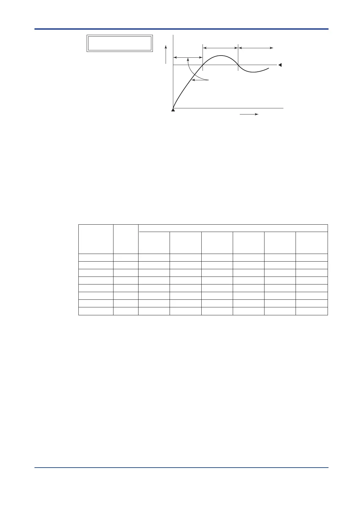
Treated
as normal
C
Power-on
Time
The alarm output does not
turn on in this region even
if the PV value is below the
low limit of the alarm setpoint.
Low limit of
alarm setpoint
Normal Abnormal
The alarm
output turns on.
Stand-by Action
It is effective in the following cases where;
- the power is turned on
- the target setpoint is changed
- the target setpoint number is switched
(however, except for remote setpoint)
- the alarm type is changed
2.8 Description of Multiple Setpoints and PID
The UT550/UT520 has a maximum of eight target setpoints, and has PID for each of these
setpoints. The following shows the correspondence between the target setpoint numbers
(SPN), target setpoints (SP), and PID parameters.
For example, if you have set “2” to the target setpoint number (SPN), the control param-
eters available are target setpoint (2.SP), proportional band (heating-side proportional
band) (2.P), integral time (heating-side integral time) (2.I), derivative time (heating-side
derivative time) (2.D), cooling-side proportional band (2.Pc), cooling-side integral time
(2.Ic), and cooling-side derivative time (2.Dc).
To use multiple target setpoints, see the table below to check the corresponding param-
eters.
PID parameter
Target setpoint
number
(SPN)
Target
setpoint
(SP)
Proportional
band
(heating-side
proportional band)
Integral time
(heating-side
integral time)
Derivative time
(heating-side
derivative time)
Cooling-side
proportional
band
Cooling-side
integral time
Cooling-side
derivative time
SPN=2 2.SP 2.P 2.I 2.D 2.Pc 2.Ic 2.Dc
SPN=3 3.SP 3.P 3.I 3.D 3.Pc 3.Ic 3.Dc
SPN=4 4.SP 4.P 4.I 4.D 4.Pc 4.Ic 4.Dc
SPN=5 5.SP 5.P 5.I 5.D 5.Pc 5.Ic 5.Dc
SPN=6 6.SP 6.P 6.I 6.D 6.Pc 6.Ic 6.Dc
SPN=7 7.SP 7.P 7.I 7.D 7.Pc 7.Ic 7.Dc
SPN=8 8.SP 8.P 8.I 8.D 8.Pc 8.Ic 8.Dc
SPN=1 1.SP 1.P 1.I 1.D 1.Pc 1.Ic 1.Dc
 Loading...


