1-2
<Toc> < 1. Installation >
IM 05D01C02-41E 3rd Edition: May 31, 2006-00
Contact input terminals Contact output terminals
Model and Suffix
Codes
DI1 DI2 DI3 DI4 DI5 DI6 DI7 DO1 DO2 DO3 DO4
UT520-07
UT520-00
UT520-08
DI8 DO5
DO6 DO7
✓
✓
✓
✓
✓
✓
✓
✓
✓
✓
✓
✓
✓
✓
✓
✓
✓
✓
✓
Note: For details on the functions of contact inputs/outputs, see “1.5 Terminal Wiring Diagrams” .
1.2 How to Install
NOTE
To install the controller, select a location where:
(1) no one may accidentally touch the terminals,
(2) mechanical vibrations are minimal,
(3) corrosive gas is minimal,
(4) temperature can be maintained at about 23°C
and the fluctuation is minimal,
(5) no direct radiant heat is present,
(6) no magnetic disturbances are caused,
(7) no wind blows against the terminal board (reference junction compensation element),
(8) no water is splashed,
(9) no flammable materials are around,
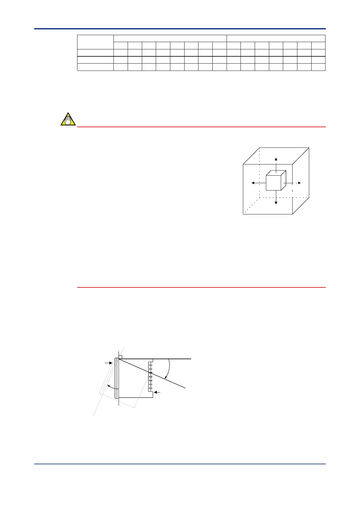
Never place the controller directly on flammable items or equipment.
If the controller has to be installed close to flammable items or equipment, be sure to
provide shielding panels all around the controller, at least 150mm away from every side;
the panels should be made of either 1.43mm-thick metal-plated steel plates or 1.6mm-thick
uncoated steel plates.
● Installation Position
Install the controller at an angle within 30° from horizontal with the front panel facing up-
ward. Do not install it facing downward. The position of right and left sides should be hori-
zontal.
Front panel
of controller
Must not
exceed 30
30
Rear of
controller
150mm150mm
150mm
150mm
 Loading...


