1-4
IM 05P02C41-01EN
1.3 ControlFunctions
Control Mode
The UP55A are controllers equipped with 5 control modes. Some control modes require
a remote input (RSP) terminal.
For the auxiliary functions of control modes, see the respective sections.
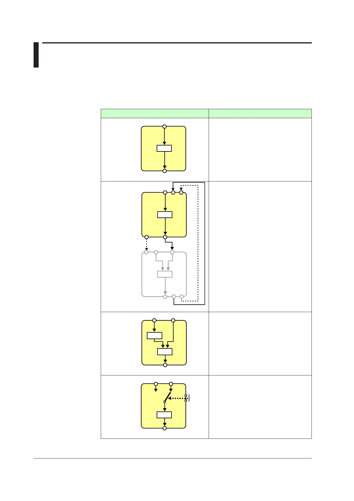
Control mode schematic diagram Description
PID
“Single-loop control” provides the basic control
function having one control computation unit.
► 8.1.1Single-loopControl,Single-loop
Heating/cooling Control, and Single-loop
Position Proportional Control
Cascade
primary-loop
control
PVSwitch
to AUTO
FAIL
TRK
PV
Cascade
RSP
OUT
DI
OUT
PID
RSP
RET DO
Primary
Secondary
PID
“Cascade primary-loop control” sets up a
controller as the primary-loop controller when
two controllers are used for Cascade control. It
is used in connection with “Cascade secondary-
loop control.” It provides the output tracking
function and FAIL output to the secondary-loop
controller.
Remote input (RSP) terminal is required for
output tracking input
► 8.1.2CascadePrimary-loopControl
Cascade control
PV1
OUT
PV2 (RSP)
PID1
PID2
“Cascade control” uses two control computation
unitsandpermitsCascadecontrolusingjusta
single controller.
Remote input (RSP) terminal is required for
Loop-2 PV input.
► 8.1.3 Cascade Control, Cascade Heating/
cooling Control, and Cascade Position
Proportional Control
Loop control
with
PV switching
PV1 PV2 (RSP)
OUT
DI
PID
“Loop control with PV switching” uses two PV
inputs, which are switched according to input
contact signals or measurement ranges.
Remote input (RSP) terminal is required for
Loop-2 PV input.
► 8.1.4 Loop Control with PV Switching,
Heating/cooling Loop Control with PV
Switching, and Position Proportional Loop
Control with PV Switching

 Loading...


