17-13
IM 05P02C41-01EN
Installation and Wiring
17
17.4.6 ContactInputWiring
CAUTION
1) Use a no-voltage contact (relay contact etc.) for external contacts.
2) Use a no-voltage contact which has ample switching capacity for the terminal's
OFF voltage (approx. 5V) and ON current (approx 1mA).
3) When using a transistor contact, the voltage at both terminals must be 2 V or
less when the contact is ON and the leakage current must be 100 µA or less
when it is OFF.
4) If there is a risk of external lightning surges, use a lightning arrester etc.
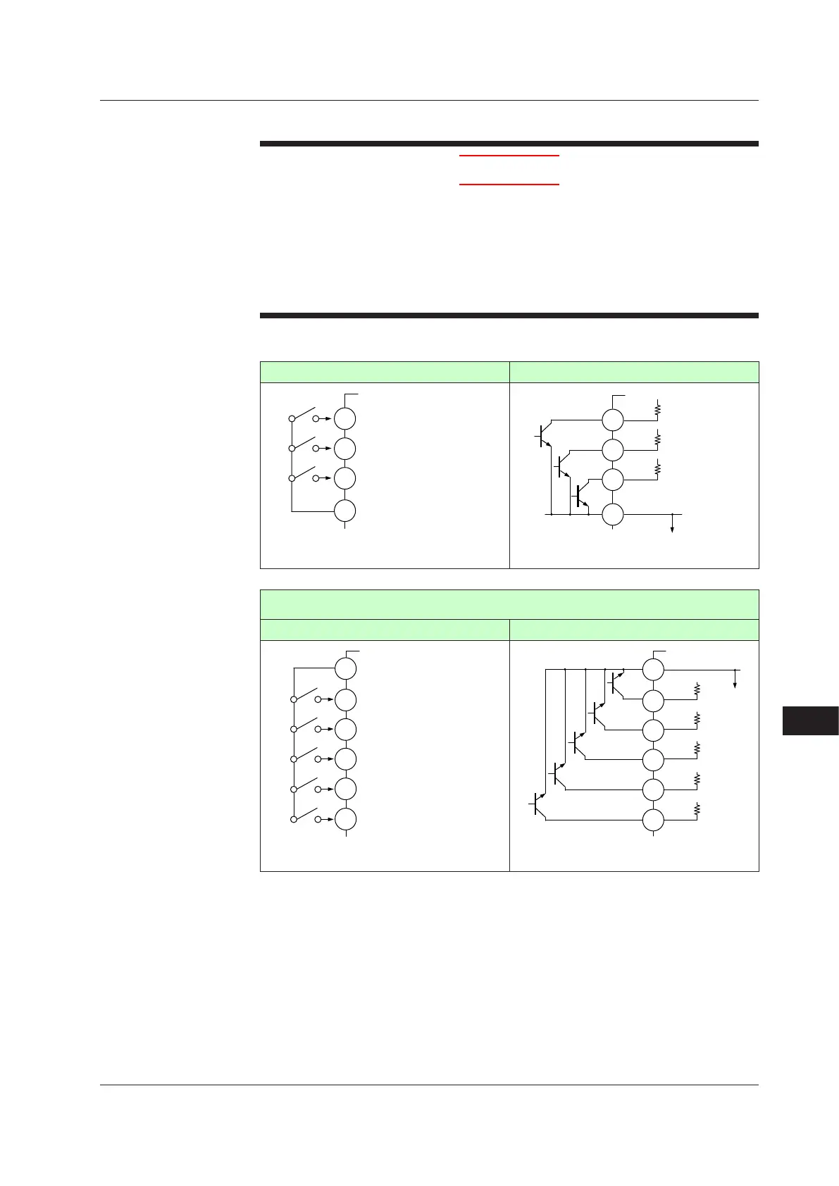
ContactInputEquippedasStandard
No-voltagecontact Transistor contact
DI3
DI2
DI1
COM
209
210
211
212
DI
Contact rating: 12 V DC, 10 mA or more
DI3
DI2
DI1
COM
209
210
211
212
+
+
+
–
+5 V
+5 V
+5 V
Contact rating: 12 V DC, 10 mA or more
Sufxcode(forStandardmodel):Type2≠2or4
Optionalsufxcode(forDetailedmodel):/X4
No-voltagecontact Transistor contact
DI41
DI42
DI43
DI44
DI45
COM
Contact rating: 12 V DC, 10 mA or more
501
502
503
504
505
506
DI41
DI42
COM
DI43
DI44
DI45
501
502
503
504
505
506
+5 V
+5 V
+5 V
+5 V
+5 V
Contact rating: 12 V DC, 10 mA or more
+
+
+
+
+
–
17.4Wiring

 Loading...


