6-34
IM 05P02C41-01EN
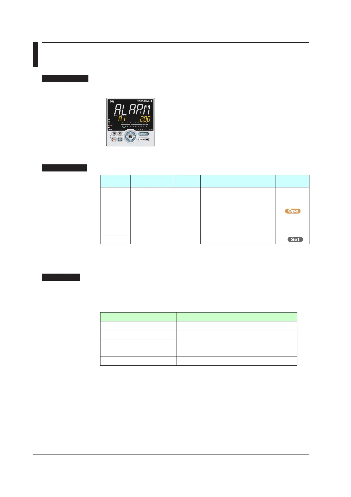
6.4 SettingAlarmSetpoint
SettingDisplay
Parameter Setting Display
Operation Display > PARAMETER key for 3 seconds (to
[MODE] Menu Display) > Rightarrow key (to [SP] Menu
Display) > SET/ENTER key (The setting parameter is
displayed.) > Downarrow key (The setting parameter is
displayed.)
SettingDetails
Parameter
symbol
Name
Display
level
Settingrange Menusymbol
A1toA8
Alarm-1 to -8
setpoint
EASY
Set a display value of setpoint of
PV alarm, SP alarm, deviation
alarm, output alarm, or velocity
alarm.
-19999 to 30000 (Set a value
within the input range.)
Decimal point position depends on
the input type
SP
ALNO. Number of alarms PRO 0 to 8 CTL
Note 1: The initial value of the parameter ALNO. is “4.” Four alarm setpoint parameters are
displayed for each SP group.
Note 2: In Cascade control, the LP2 lamp is lit while the Loop-2 parameter is displayed.
Description
These alarms work irrespective of the operation mode.
Each alarm type has eight alarm setpoints.
In Cascade control, each alarm type has eight setpoints for Loop 1 and Loop 2,
respectively.
Alarm-relatedparameter Numberofsettings
Alarm type 8 (number of settings) x 2 (number of loops)
PV velocity alarm time setpoint 8 (number of settings) x 2 (number of loops)
Alarm hysteresis 8 (number of settings) x 2 (number of loops)
Alarm delay timer 8 (number of settings) x 2 (number of loops)
Alarm setpoint 8 (number of settings) x 2 (number of loops)
► Alarmtype:Chapter11AlarmFunctions

 Loading...


