EasyManua.ls Logo

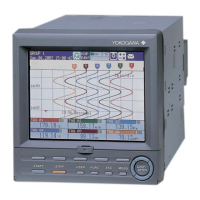
YOKOGAWA FX106 - User Manual

YOKOGAWA FX106
263 pages
To Next Page IconTo Next Page
Loading...
User’s
Manual
Yokogawa Electric Corporation
Model FX103/FX106/FX112
FX100
Model FX103/FX106/FX112
FX100
IM 04L20A01-01E
4th Edition

Table of Contents

Question and Answer IconNeed help?

Do you have a question about the YOKOGAWA FX106 and is the answer not in the manual?

YOKOGAWA FX106 Specifications

General IconGeneral
BrandYOKOGAWA
ModelFX106
CategoryController
LanguageEnglish

Summary

Safety Precautions

Precautions Related to the Protection, Safety, and Alteration of the Product

Details safety symbols and precautions for handling and modifying the product.

Checking the Contents of the Package

Chapter 1 Explanation of Functions

1.2 Functions of the Input Section

Details various input types, computations, and signal processing like difference and square root.

1.3 Alarm Function

Explains alarm generation, types, conditions, and output relay configurations.

1.4 Display Function

Covers screen layouts, data display modes (trend, digital, bar graph), and status indications.

1.5 Data Storage Function

Describes types of data (display, event, report), file formats, and storage methods.

1.6 Computation Function and Report Function (M1, PM1 Option)

Details setting computing equations, constants, tags, and generating reports.

Chapter 2 Installation and Wiring

2.2 Installation

Provides guidance on selecting an appropriate installation location and panel mounting procedures.

2.3 Measurement Input Terminal Wiring

Covers precautions and procedures for connecting measurement signal wires to terminals.

2.4 Optional InputOutput Terminal Wiring

Details wiring for optional terminal blocks like alarm relays and remote control.

2.5 Wiring the Power Supply

Details power supply connections, precautions, and switch specifications.

Chapter 3 Names of Parts, Display Modes, and Common Operations

3.2 Basic Key Operations

Explains how to navigate between operation modes and use the keys for settings.

Chapter 4 Measurement Input and Alarm Setup Operations

4.1 Setting Parameters Related to Measurement Inputs

Covers A/D integral time, scan intervals, burnout detection, RJC, and input ranges.

4.2 Setting Alarm Related Parameters

Details alarm output relay actions, indication behaviors, rate-of-change intervals, and hysteresis.

Chapter 5 Operations on the Operation Screens

5.1 Displaying Measured Data in Waveform, Numerical Values, or Bar Graph (Trend, Digital, and Bar Graph Screens)

Explains how to view data in trend, digital, and bar graph screens, including group and auto-scroll.

Chapter 6 Operations for Changing the Displayed Contents

Chapter 7 Data SaveLoad Operations

7.1 Setting Measured Data Acquisition to the Internal Memory and Data Save to the External Storage Medium

Details configuring data acquisition modes (auto/manual) and saving data to external storage.

7.3 Saving Data to the External Storage Medium (Only for Models with an External Storage Medium Drive)

Covers manual and auto save procedures for CF memory cards and floppy disks.

Chapter 8 Computation and Report Function Related Operations (M1 or PM1 Option)

8.1 Assigning Computation Channels and Setting Computing Equations, Constants and Tags

Details setting computation channels, writing equations, defining constants, and assigning tags.

8.2 Starting, Stopping, and Resetting the Computation

Explains how to start, stop, reset computations, and clear computation dropout indications.

8.3 Setting Computation Channel Alarms

Describes how to configure alarms (high/low limit, delay, difference) for computed values.

8.4 Setting the Timer for Statistical Computations (TLOG Computation) and Data Save (TLOG Data)

Covers timer settings for TLOG computation and interval-based data saving.

Chapter 9 Operations of Other Functions

Chapter 10 Troubleshooting

10.1 A List of Messages

Provides a comprehensive list of error codes, messages, and their explanations/countermeasures.

10.2 Troubleshooting Flow Chart

Offers a visual guide for diagnosing and resolving common operational problems.

Chapter 11 Maintenance

Chapter 12 Specifications

Appendix 3 Pulse Measurement Setting Example (Pulse Sum Value Reset If It Exceeds a Fixed Value) (PM1 Option)

Appendix 6 List of Parameters

Related product manuals