7-9
IM 05P02C41-01EN
Input (PV, Remote, and Auxiliary Analog) Functions
(2)SettingSquareRootExtractionandLowSignalCutoffPoint
Description
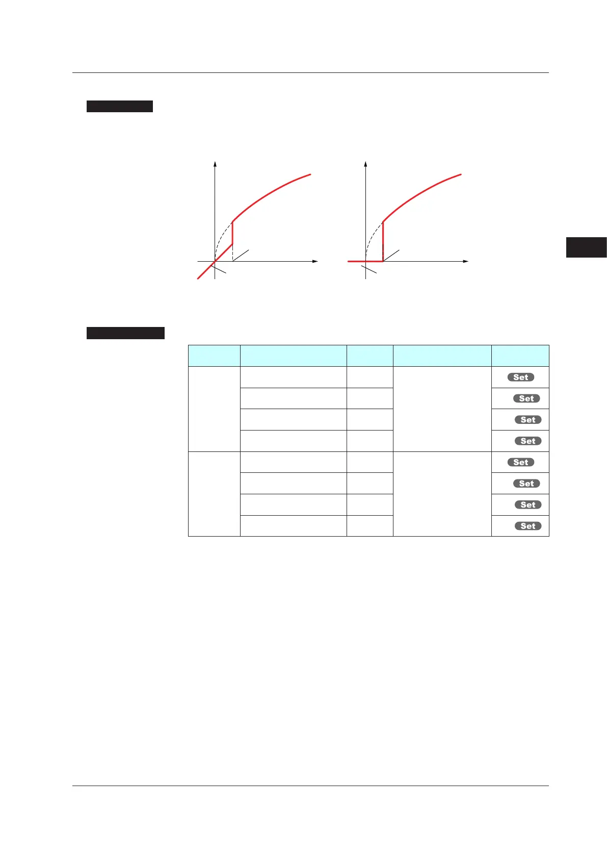
This calculation is used to convert, for example, a differential pressure signal from a
throttlingflowmetersuchasanorificeandnozzleintoaflow-ratesignal.Thereisno
hysteresis for low signal cutoff point.
Output = Input
The slope equals “1” at levels below
the low signal cutoff point (A.SR=1).
The slope equals “0” at levels below
the low signal cutoff point (A.SR=2).
Output
Input
Output = Input
Output
Input
Low signal cutoff
point is variable.
Low signal cutoff
point is variable.
SettingDetails
Parameter
symbol
Name
Display
level
Settingrange Menusymbol
A.SR
PV analog input square root
extraction
PRO
OFF: No square root extraction.
1: Compute the square root.
(The slope equals “1.”)
2: Compute the square root.
(The slope equals “0.”)
PV
RSP analog input square
root extraction
PRO RSP
AIN2 aux. analog input
square root extraction
PRO AIN2
AIN4 aux. analog input
square root extraction
PRO AIN4
A.LC
PV analog input low signal
cutoff
PRO
0.0 to 5.0%
PV
RSP analog input low signal
cutoff
PRO RSP
AIN2 aux. analog input low
signal cutoff
PRO AIN2
AIN4 aux. analog input low
signal cutoff
PRO AIN4
Note 1: When each parameter is displayed, the terminal area (E1 to E4) is displayed on Group
display according to the suffix code and optional suffix code.
Note 2: Each parameter is displayed when the input type is voltage or current.
7
7.1SettingFunctionsofPVInput,RemoteInput,andAuxiliaryAnalogInput

 Loading...


