7-8
IM 05P02C41-01EN
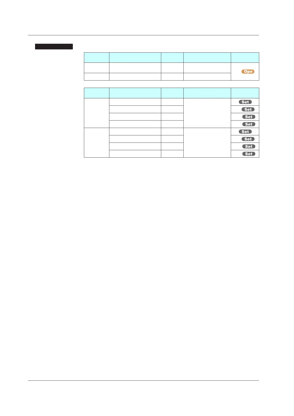
SettingDetails
Parameter
symbol
Name
Display
level
Settingrange Menusymbol
BS PV input bias EASY
-100.0 to 100.0% of PV
input range span (EUS)
PVS
FL PVinputlter EASY OFF, 1 to 120 s
Parameter
symbol
Name
Display
level
Settingrange Menusymbol
A.BS
PV analog input bias STD
-100.0 to 100.0% of each
input range span (EUS)
PV
RSP analog input bias PRO RSP
AIN2 aux. analog input bias PRO AIN2
AIN4 aux. analog input bias PRO AIN4
A.FL
PVanaloginputlter STD
OFF, 1 to 120 s
PV
RSPanaloginputlter PRO RSP
AIN2aux.analoginputlter PRO AIN2
AIN4aux.analoginputlter PRO AIN4
Note 1: BS, FL; In Cascade control, PV input terminal is for Loop 1 and RSP remote input terminal
is for Loop 2. The LP2 lamp is lit while the Loop-2 parameter is displayed.
Note 2: When each parameter is displayed, the terminal area (E1 to E4) is displayed on Group
display according to the suffix code and optional suffix code.
7.1SettingFunctionsofPVInput,RemoteInput,andAuxiliaryAnalogInput

 Loading...


