7-1
IM 05P02C41-01EN
Input (PV, Remote, and Auxiliary Analog) Functions
7
7.1 SettingFunctionsofPVInput,RemoteInput,
andAuxiliaryAnalogInput
7.1.1 SettingInputType,Unit,Range,Scale,andDecimalPointPosition
Description
The figure below describes the case of PV input. The remote input and auxiliary analog
input can be set in the same way.
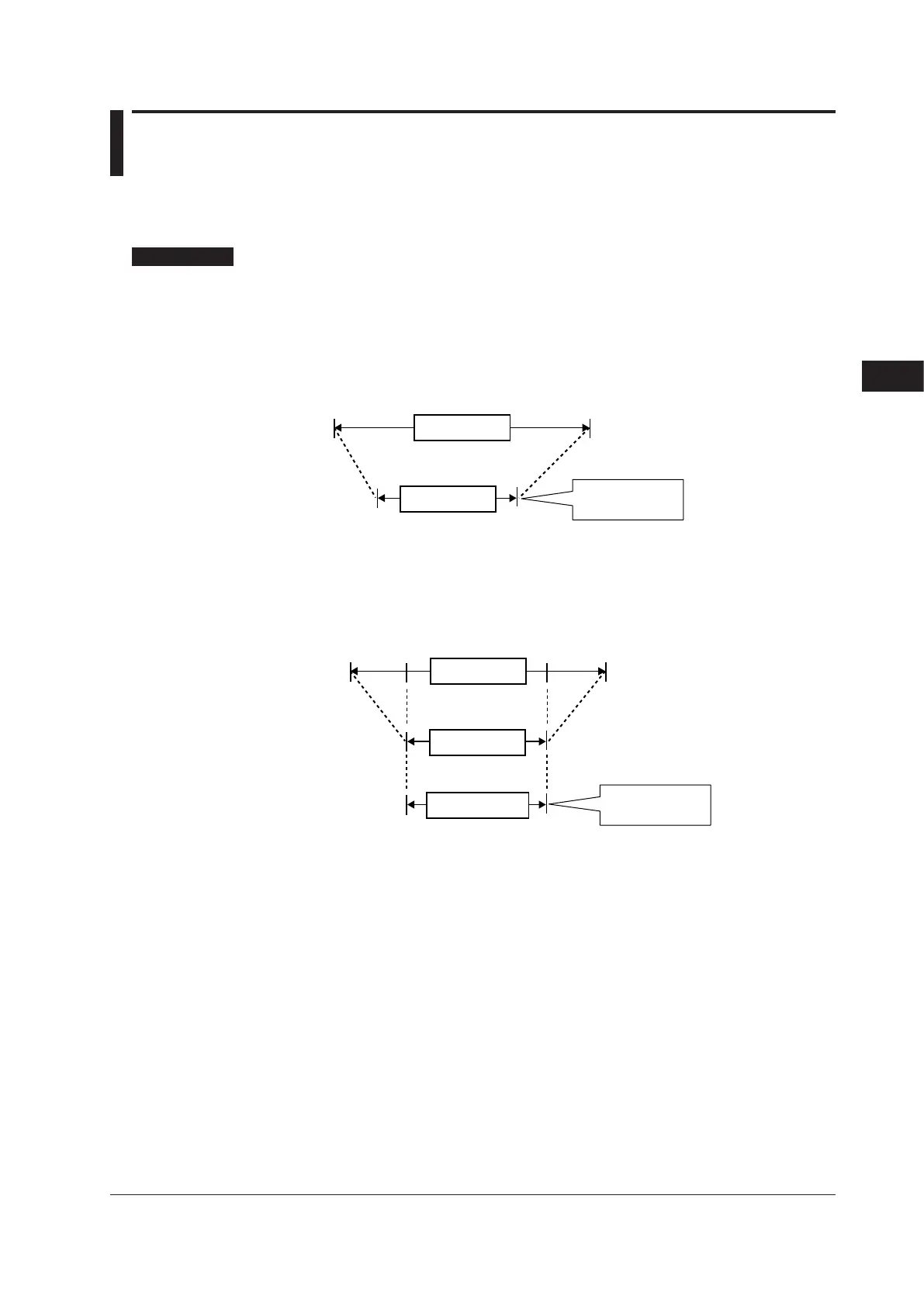
ExampleofTemperatureInput
The figure below is an example of setting Type K thermocouple and a measurement
range of 0.0 to 800.0 ºC.
Minimum value of PV input range
Input type
RL = 0.0°C RH = 800.0°C
Maximum value of PV input range
Set a range to be
controlled.
PV input range
ExampleofVoltageandCurrentInputs
The figure below is an example of setting 2-4 V DC and a scale of 0.0 to 50.0 m³/h.
Minimum value of PV input scale
1 V 5 V
(input signal)
SL = 0.0 m³/h SH = 50.0 m³/h
Maximum value of PV input scale
2 V 4 V
RL = 2.000
RH = 4.000
RH = 5.000
PV input scale
Input type
Set a range to be
controlled.
PV input range
When using 1-5 V DC signal as is, set RH = 5.000 V, RL = 1.000 V, SDP=1, and SH =
50.0, and SL=0.0.
Chapter7Input(PV,Remote,andAuxiliaryAnalog)Functions

 Loading...


