7-5
IM 05P02C41-01EN
Input (PV, Remote, and Auxiliary Analog) Functions
7
7.1.2 SettingBurnoutDetectionforInput
Description
The input value when input burnout occurs can be determined.
The input value is 105.0% of the input range when the upscale is set, and -5.0% of the
input range when the downscale is set.
Burnout detection is activated for TC, RTD, and standard signal (0.4–2 V or 1–5 V).
For standard signal, burnout is determined to have occurred if it is 0.1 V or less for the
range of 0.4–2 V and 1–5V, or if it is 0.4 mA or less for the range of 4–20 mA.
When input burnout occurs, the error preset output (EPO) is output as control output.
► Inputerrorpresetoutput:10.12.3SettingOutputValueWhenErrorOccurs(InputErrorPreset
Output)
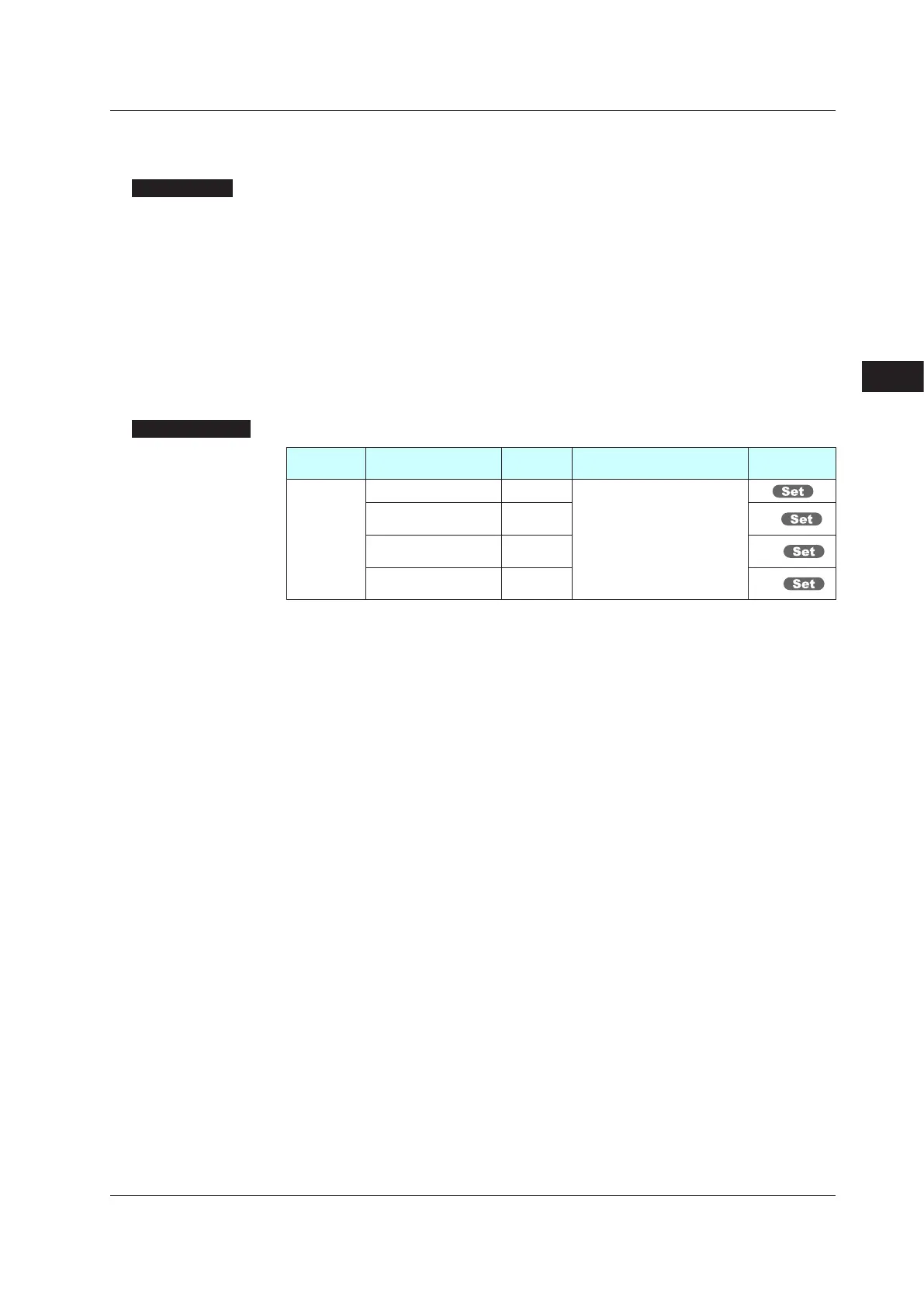
SettingDetails
Parameter
symbol
Name
Display
level
Settingrange Menusymbol
BSL
PV input burnout action STD
OFF: Disable
UP: Upscale
DOWN: Downscale
PV
RSP remote input
bumout action
STD RSP
AIN2 aux. analog input
burnout action
STD AIN2
AIN4 aux. analog input
burnout action
STD AIN4
Note 1: When each parameter is displayed, the terminal area (E1 to E4) is displayed on Group
display according to the suffix code and optional suffix code.
7.1SettingFunctionsofPVInput,RemoteInput,andAuxiliaryAnalogInput

 Loading...


