17-11
IM 05P02C41-01EN
Installation and Wiring
17
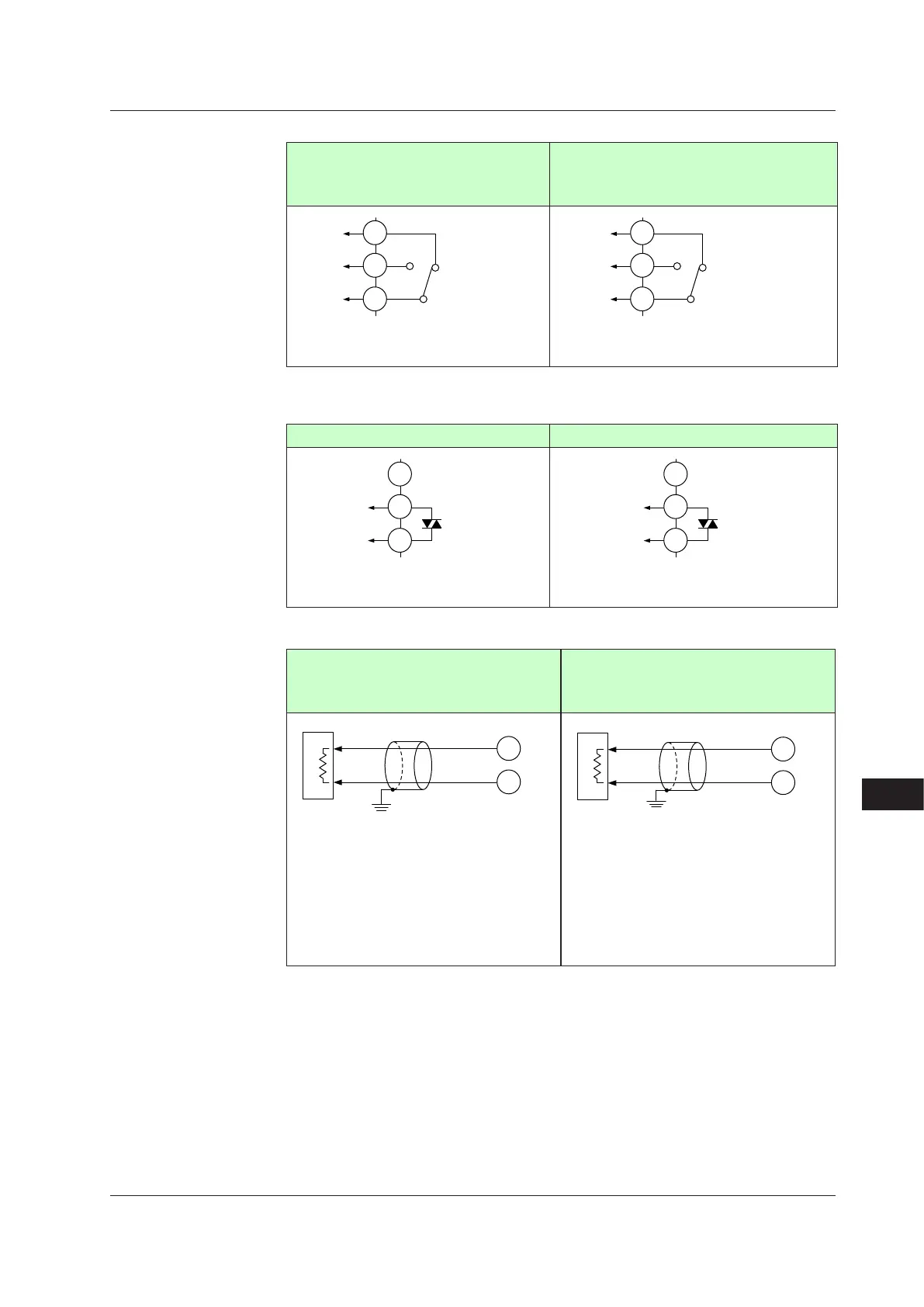
RelayOutput
(ForStandardmodel)Standardtypeoutput
orHeating/coolingtypeheating-sideoutput
(ForDetailedmodel)SufxcodeofOutput
1=“-R”or“-U”
(ForStandardmodel)Heating/coolingtype
cooling-sideoutput
(ForDetailedmodel)SufxcodeofOutput2=
“R”or“U”
NC
NO
101
102
103
OUT
Contact rating: 250 V AC, 3 A
30 V DC, 3 A (resistance load)
NC
NO
507
508
509
OUT2
Contact rating: 250 V AC, 3 A
30 V DC, 3 A (resistance load)
Note: The control output should always be used with a load of 10 mA or more.
TriacOutput(forDetailedmodel)
SufxcodeofOutput1=“-T” SufxcodeofOutput2=“T”
OUT
NO
101
102
103
Contact rating: 75-250 V AC
Allowable load current: 0.8 A
OUT2
NO
507
508
509
Contact rating: 75-250 V AC
Allowable load current: 0.8 A
CurrentandVoltagePulseOutput
(ForStandardmodel)
Standardtypeor
Heating/coolingtypeheating-sideoutput
(ForDetailedmodel)SufxcodeofOutput1=
“-A”or“-U”
(ForStandardmodel)Heating/coolingtype
cooling-sideoutput
(ForDetailedmodel)SufxcodeofOutput2=
“A”or“U”
208
207
–
+
Control valves
(or other
actuators)
Current:
4 to 20 mA DC or
0 to 20 mA DC
(resistance load: 600 Ω or less)
Voltage pulse:
On-voltage: 12 V DC or more
(load resistance: 600 Ω or more)
Off-voltage: 0.1 V DC or less
Grounding
512
511
–
+
Current:
4 to 20 mA DC or
0 to 20 mA DC
(resistance load: 600 Ω or less)
Voltage pulse:
On-voltage: 12 V DC or more
(load resistance: 600 Ω or more)
Off-voltage: 0.1 V DC or less
Grounding
Control valves
(or other
actuators)
Use
When current/voltage pulse output is not used for control output, it can be used for
retransmission output.
When retransmission output terminal is not used for retransmission output, it can be used
for optional control output. The current output range can be changed.
For control output setting, set the control mode (CTLM) and the control type (CNT), then
set the output terminal and output type in the output type selection (OT).
► Controloutputtype:10.1SettingControlOutputType
17.4Wiring

 Loading...


