6-3
IM 05P02C41-01EN
Monitoring and Control of Regular Operations
6
TSP Display
Remaining Segment-time Display
Segment Number Display
Remaining Repetition Display
Program Pattern Display
program pattern (overview)
Can be changed by parameter PTSL.
(Factory default: non-display)
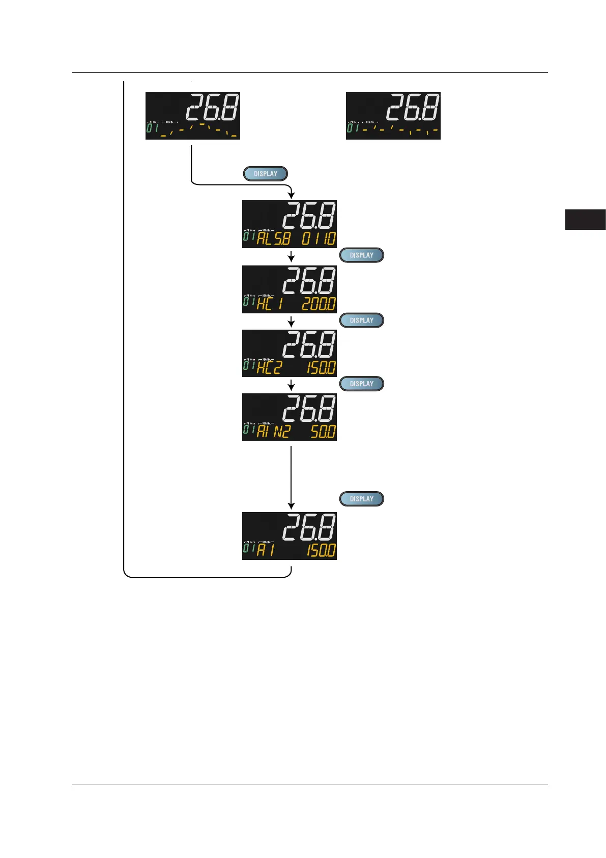
Alarm-5 to -8 Status Display (display only)
Displays "SSP" during reset-mode.
Displays "L.SP" during local-mode operation.
Displays "R.SP" during remote-mode operation.
Displays during program operation.
(When the program pattern-2 retransmission is selected (PT2.G=ON).)
Displays "SSP" during reset-mode.
Displays "L.SP" during local-mode operation.
Displays "L.SP" during remote-mode operation.
LP2 lamp is lit.
SP Display
TSP Display
(When the program pattern-2 retransmission is selected (PT2.G=ON).)
Displays during program operation.
LP2 lamp is lit.
Displays during program operation.
When the pattern number is 0, 0/0 is displayed.
Dispalys the number of remaining repetitions (R.CYC) on Setpoint display.
This display is displayed only when the repeat function is set and the
operation mode is PROG.
When pattern number is
0, pattern is not
displayed.
0: On, 1: On
Ex.: Alarm 5: Off, Alarm 6: On, Alarm 7: On,
Alarm 8: Off
SP Display
OUT Display
PID Number Display (display only)
(Factory default: non-display)
Heater Break Alarm-1 Current Display (display only)
(Only for Heater break alarm option)
Heater Break Alarm-2 Current Display (display only)
(Only for Heater break alarm option)
SELECT Displays 1 to 5
(Displayed only when SELECT Display is registered.
(The figure on the left is the example of
the parameter A1 (alarm-1 setpoint).)
Analog Input Displays (display only)
(Factory default: non-display)
PV: PV analog input,
RSP: RSP analog input (E1-terminal area),
AIN2: AIN2 analog input (E2-terminal area),
AIN4: AIN4 analog input (E4-terminal area)
(Only for each aux. analog input)
(OUT can be changed in MAN mode.)
6.1MonitoringandControlofOperationDisplays

 Loading...


