55
IM 01B08B02-01EN
Installation and Wiring
Installation and Wiring
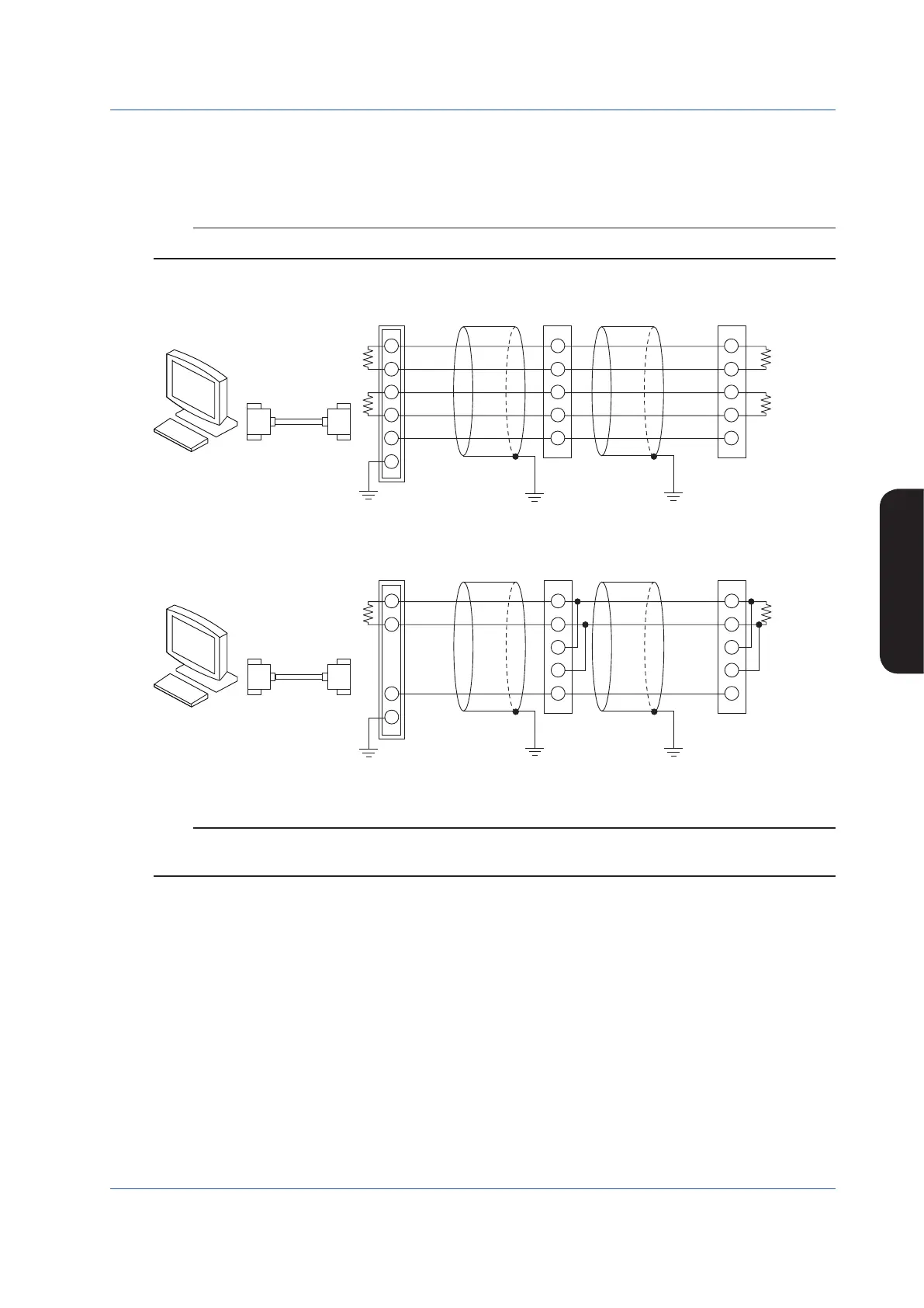
Wiring for the Serial Communication Interface (Optional Code /A31)
To perform Modbus communication, PC-link communication, or YS protocol communication connect the wires as shown below.
To perform YS protocol communication with DCS, connect the wires as a four-wire type shown below.
If the instrument is located at the end of the wiring, turn ON the terminating resistor. The terminating resistance (internal) can be
set using the RS-485 communication terminating resistor ON/OFF (TRMR) engineering parameter.
Note
Even if the terminating resistor is being ON, it will be OFF when the power supply of the instrument is turned off.
► For details of communication parameter setting and communication functions: see YS1000 Series Communication Interface User’s Manual
Four-wireconnection
SG
SDB (+)
SDA (−)
RDB (+)
RDA (−)
RDB (+)
RDA (−)
SDB (+)
SDA (−)
SG
Communication cable
18
17
16
15
14
2
1
4
3
5
6
18
17
16
15
14
Ground Ground Ground
resistor
(internal),
120 Ω
resistor
(external),
120 Ω
PC
Terminating
resistor
(external),
120 Ω
RS-232C
straight cable
Communication cable
Figure 9.19
Two-wireconnection
SG
B (+)
A (−)
SDB (+)
SDA (−)
RDB (+)
RDA (−)
SG
16
15
4
3
5
6
18
17
14
16
15
18
17
14
Communication cable
resistor
(internal),
120 Ω
Communication cable
PC
Terminating
resistor
(external),
120 Ω
RS-232C
straight cable
Ground GroundGround
Figure 9.20
Note
ML2- is a YOKOGAWA converter. RS-232C/RS-485 converters other than these devices can also be used. In such a case,
check the electric specifications of each converter, etc. before using them.

 Loading...


