53
IM 01B08B02-01EN
Installation and Wiring
Installation and Wiring
Wiring for Digital Input/Output and FAIL Output
WARNING
For products with optional code /FM or /CSA:
Install explosion-proof wiring defined in the relevant country for the following signal wiring.
• The digital output cable must be wired from the non-hazardous area by using Class I, Division 2 wiring dedicated in
potentially explosive atmospheres such as a threaded metal conduit. In addition, it is necessary to be wired not to apply
stress at the end of the cable.
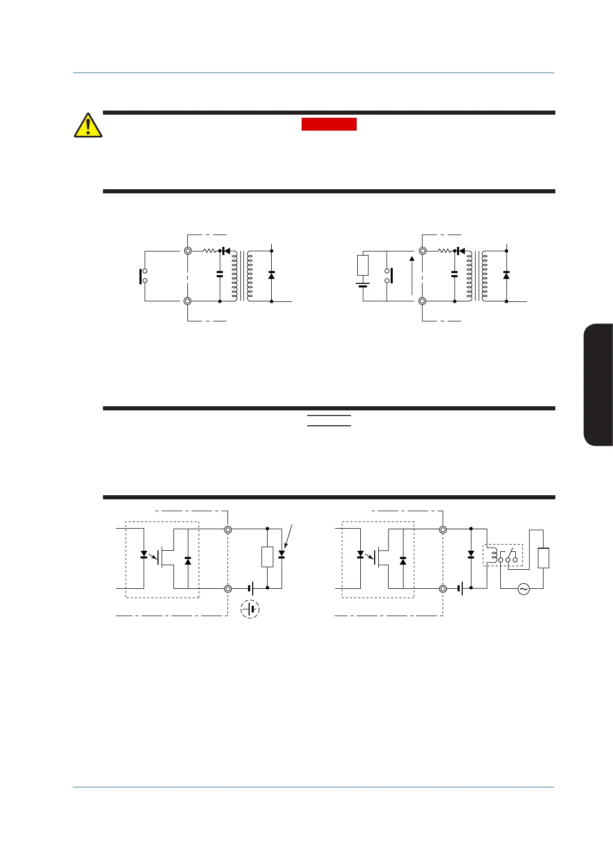
External no-voltage and voltage contacts for digital inputs should be provided so that the rated value is obtained. Attention must
be paid to excessive conductor resistance and in-conductor voltage drop.
YS1000
Rated value
ON: 200 Ω or less
OFF: 100 kΩ or more
0915E.ai
Figure 9.13 Connection of Digital Input (No-voltage Contact)
V
Rated value
ON: V = −0.5 to +1 V
OFF: V = 4.5 to 30 V
Load
Figure 9.14 Connection of Digital Input (Voltage Contact)
When driving an external device using contact outputs such as alarm output, status output, and FAIL output, install wiring paying
attention to the following:
CAUTION
• Do not connect loads exceeding the contact rating.
• To drive equipment incorporating inductance components such as relays, always connect a protective diode (surge
absorber) in parallel with the load.
• To connect a power supply for driving a load, the power supply’s polarity must be matched with that of the contact
output. Connecting it in reverse may result in failure.
• An AC load cannot be directly opened or closed using contact output. In this case, provide a repeating relay, etc.
YS1000
Rated value
30 V DC or less
200 mA or less (resistive load)
0917E.ai
Protective diode
External
(24 V DC)
This connection
cannot be made.
Load
−
+
Figure 9.15 Connection Using Digital Output
External
power supply
(24 V DC)
Relay
+
–
AC power
supply
Figure 9.16 Connection of Digital Output to Drive a Load Including AC
Power Supply

 Loading...


