52
IM 01B08B02-01EN
Installation and Wiring
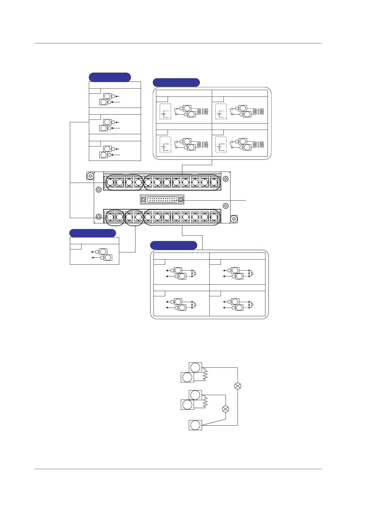
ExpandableI/OTerminalDiagram(YS1700BasicType(withExpandable I/O))
Note: *Do not use unassigned terminals as relay terminals.
X6
+
1
-
2
X7
+
3
-
4
X8
+
13
-
14
Y4
+
15
-
16
DI7
+
5
-
6
DI8
+
7
-
8
DI9
+
9
-
10
DI10
+
11
-
12
DO7
DO8
DO9
DO10
+
17
-
18
+
19
-
20
+
21
-
22
+
23
-
24
Analog input 6
Digital input 7
Digital input 8
Digital input 9
Digital input 10
Analog input 7
Analog input 8
Analog output 4
Digital output 7
Digital output 8
Digital output 9
Digital output 10
If the terminals concerned are
used as digital output, an external
power supply is required.
► For digital output wiring: see
“Wiring for Digital Input/Output
and FAIL Output” described later.
specifications:
Rating 30V DC
200 mA or less
(resistive load)
1
13 14 15 16 17 18 19 20 21 22 23 24
2 3 4 5 6 7 8 9 10 11 12
Analog Inputs
Digital Inputs
Voltage
input
(1-5 V DC)
Voltage
input
(1-5 V DC)
Voltage
input
(1-5 V DC)
Voltage
output
(1-5 V DC)
The digital input functions are not set
when shipped from the factory.
The functions can be set using the DI7F
to DI10F engineering parameters.
The digital output functions are not set
when shipped from the factory.
The functions can be set using the DO7F
to DO10F engineering parameters.
When voltage is present
ON: −0.5 to 1 V DC
OFF: 4.5 to 30 V DC
For no voltage
ON: resistance of
200 Ω or less
OFF: resistance of
100 kΩ or more
Input contact rating:
5 V DC,
20 mA or more
With
voltage
With
voltage
With
voltage
With
voltage
To the rear terminals of the
YS1700 main unit
YS1700-01
only
Analog Outputs
Digital Outputs
Measurement input 1 is output in the
cascade/selector mode.
The analog output type can be
changed in the Y4S Engineering
parameter.
Analog input 6 is
output tracking
input in
cascade/selector
mode.
Figure 9.11
Transmitter Supply Power Wiring
If the YS1000 is connected to a two-wire transmitter, it is recommended that the field signal be isolated to limit the effects of short
circuiting or ground fault incidents within a narrow range. (Use an external distributor.)
However, for economical connection to a two-wire transmitter, the YS1000 is equipped with non-isolated power terminals for
transmitters (25 to 25.5 V DC).
−
+
250Ω
3W
Measurement input 1
Measurement input 2
24 V DC
supply power
1
250Ω
3W
−
+
2
5
6
13
Figure 9.12
Supply current
When optional specification direct input (/A0) is provided: 25 to 25.5 V DC, 30 mA
When no optional specification direct input (/A0) is provided: 25 to 25.5 V DC, 60 mA (two two-wire transmitters can be con-
nected)

 Loading...


