62
IM 01B08B02-01EN
Troubleshooting
Selecting the action to take in the event of an error in the circuit diagnosis of current output.
Description
The SCOCD parameter is enabled when using Y1 terminal or Y3 terminal (Y3TP (analog output 3 current/voltage switching) is
4-20 mA (0)).
This parameter can be used to select D/A FAIL or OOP ALARM for displaying the diagnostic result in the event of an error with the
D/A conversion section and read-back value. Note that selecting OFF (2) does not perform diagnosis.
When Y terminal is voltage output (Y2 terminal, Y4 terminal, or Y3 terminal (Y3TP (analog output 3 current/voltage switching) is
1-5V (1)), D/A FALL is displayed if an error occurs with the D/A conversion section, regardless of the setting of SCOCD.
Current output wire open is detected, regardless of the setting of SCOCD.
Setting Display
Parameters Names Setting Range
Factory
Default
Display
SCOCD
Selection of Current
Output Circuit Diagnosis
FAIL: D/A FALL in the event of an error
ALARM: OOP ALARM in the event of an error
OFF: No diagnosis
ALARM
Engineering
Menu Display
1 > [CONFIG1]
(Configuration
Display 1)
Note
• How to use the Selection of Current Output Circuit Diagnosis (SCOCD)
When SCOCD is in ALARM (1) (default value):
If an error is detected in the current output read-back value, OOP ALARM is issued and control is continued. In the event
of a breakdown of the current output circuit, control is also continued. In this case, a breakdown of the current output
circuit should be judged based on the fact that proper control can no longer be performed or another system alarm or
process alarm has been issued.
When SCOCD is in FAIL (0):
If a breakdown of the current output circuit or an error in the current output read-back value is detected, D/A FAIL is set
and control is stopped.
When SCOCD is in OFF (2):
Control continues, even if an output read-back value error occurs or the current output circuit breaks down. In this
case, a breakdown of the current output circuit should be judged based on the fact that proper control can no longer be
performed or another system alarm or process alarm is issued.
• Diagnosis of the current output circuit
In current output circuit diagnosis, the current output value of the Y1 or Y3 terminal is read back to within the YS1000 to detect
an error from a difference between the output value and read-back value.
There are cases where the read-back value does not agree with the output value temporarily due to the characteristics of
a positioner, etc. connected to the Y1 or Y3 terminal or noise superimposed by the wiring condition, which results in the
judgment that there is an error in the D/A conversion section.
However, temporary noise of this kind or low-level noise may not affect control and control may be continued normally.
If an error occurs in the D/A conversion section, the cause may be one of the following three. Take action according to each
cause.
Possible Cause Actions
(1) Breakdown of the current
output circuit
In this case, control is disabled from being continued.
The current output circuit has failed; contact us for repair.
(2) A break in wire of Y1 or Y3
terminal
A wire of the Y1 or Y3 terminal has broken; check the wiring.
This error may also occur if a terminal wire is disconnected during maintenance,
transient work, etc.
(3) Noise on Y1 or Y3 terminal Ifcontrolisaected,eliminatenoise.
If control is normal, control can be continued as is. This presents no problem.
Backup Operation in the Event of Instrument Failure
Hardmanualunitoperation(exceptincaseswhensuffixcode-2
was specified)
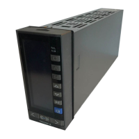
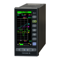
Swinging up the front panel allows you to see the control section of the hard manual unit for backup (a manual operation output
section consisting of analog circuits) on the internal panel.
If YS1000 is in FAIL status and there is an urgent demand situation, set the manipulated output variable (Y1 output) to the safe
side using hard manual unit operation.
 Loading...

